Applications 83
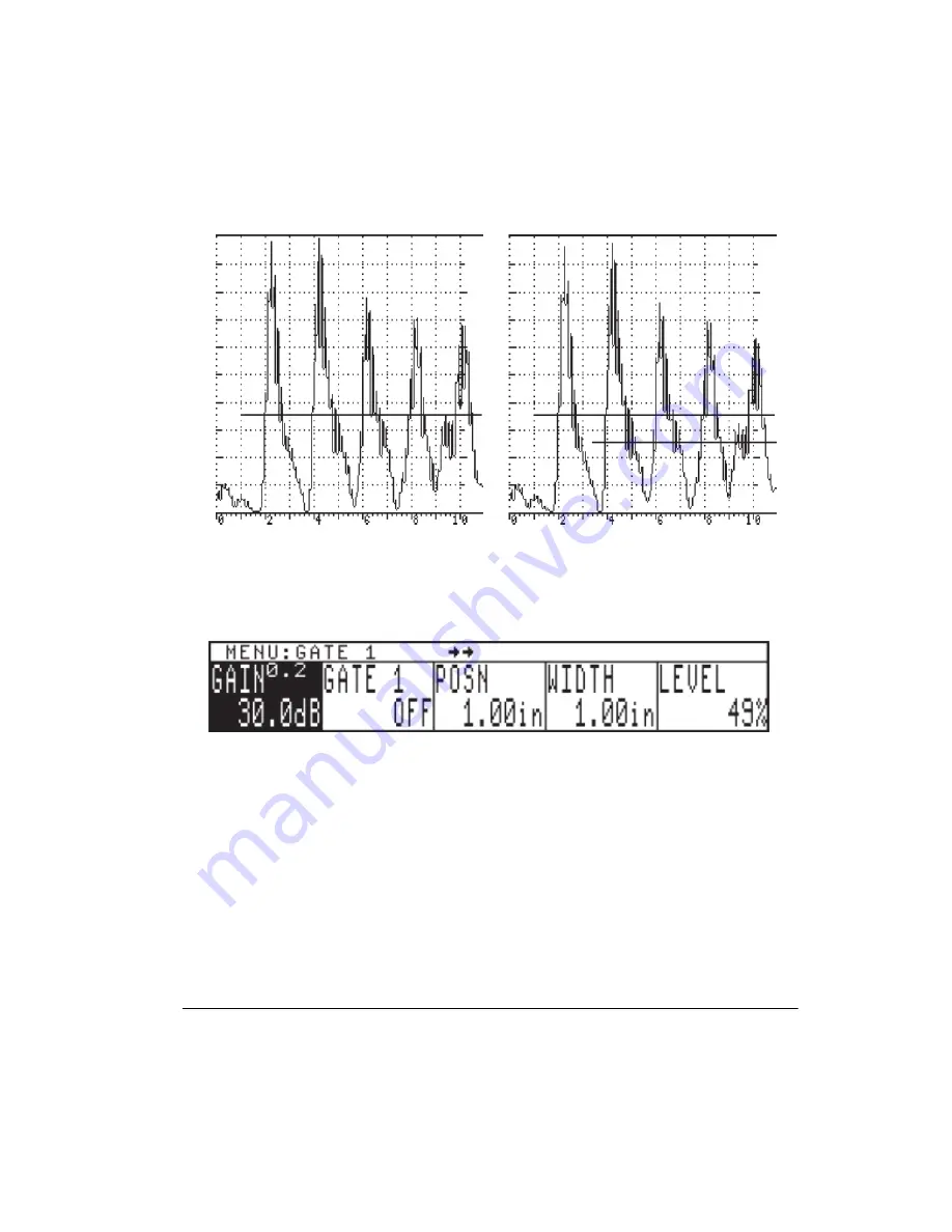
wide enough to cover the area where the 2nd back wall echo will appear (see
Figure 5-13)
.
Figures 5-12 and 5-13
Press GATE1 menu key and the following menu will appear. This menu provides changeable
parameters, such as Polarity, Position, Width, and Level, for either flaw or thickness
measurements of Gate1.
For thickness measurements, adjust the controls as follows.
1.
To enable Gate1, press GATE1 menu key again and rotate the SmartKnob™ to select the
“+” Gate1 alarm.
2.
Press the Gate LEVEL
menu soft key
and rotate the SmartKnob™ to the desired screen
height, such as 35%.
3.
Press the Gate POSN
menu soft key
and rotate the SmartKnob™, or press the POSN
menu
soft key
repeatedly, so that the start of the gate is to the left of the thinnest step (0.200
inch). (Please refer
to
Figure 5-14
)
.
4.
Press the Gate WIDTH
menu soft key
and rotate the SmartKnob™, or press the WIDTH
menu soft key
repeatedly, to adjust the Gate width until it goes past or through the 1st echo
from the thinnest step (see
Figure 5-15
)
.
Summary of Contents for Sonic 1200S/HR
Page 1: ...PN 7720044 PN 7720066 March 2006 Sonic 1200S HR Ultrasonic Flaw Detector User s Manual...
Page 8: ......
Page 13: ...Preparation for Operation 5 1 2 Sonic 1200S HR Packages 1 2 1 Sonic 1200S Packages...
Page 14: ...6 Chapter 1...
Page 15: ...Preparation for Operation 7 1 2 2 Sonic 1200HR Packages...
Page 16: ...8 Chapter 1 1 3 Sonic 1200S HR Packages 1 3 1 Sonic 1200S Packages...
Page 17: ...Preparation for Operation 9...
Page 18: ...10 Chapter 1 1 3 2 Sonic 1200HR Packages...
Page 36: ...28 Chapter 2...
Page 72: ...64 Chapter 4...
Page 110: ...102 Chapter 5 Figure 5 37 IIW Type 1 Block Echoes Figure 5 38 IIW Type 2 Block Echoes...
Page 119: ...Applications 111 f Calibration is now done see Figure 5 50 Figure 5 48 Figure 5 49...
Page 134: ...126 Chapter 6...
Page 149: ...Computer Interface 141...


