background image

44    Chapter 4

wideband, 10 MHz tuned settings, and all RF displays to limit screen noise. The gain setting is
a relative value and does not reflect actual overall signal gain.

The instrument’s +dB feature is toggled OFF and ON alternately by pressing the gain soft key
when the gain parameter is highlighted. A +dB icon is shown in the status portion of the
display if this feature is active.

DB DIFF

 Allows the operator to establish a gain reference for signal amplitude comparison.

Pressing this soft key will force the instrument DB DIFF value to +0.0 dB. The DB DIFF value
will track all future changes in the gain value (+/-).

DISPLAY

 Selects the type of video. Available modes are positive halfwave “HALF+”,

negative halfwave“HALF-”, fullwave “FULLWAV”, “RF”, “RF+”(HR), “RF-”(HR), and
display filter functions (FILTR1, FILTR2, and FILTR3). Filters are only accessible with
software revision R00A or greater.

FREQ

 Selects the frequency of operation of the receiver filtering circuitry. Selections are

1MHz, 2.25 MHz, 5 MHz, 10 MHz, 15 MHz (HR), WIDEBAND (0.3 - 15 MHz), and HIPASS
(3 - 15 MHz). When the frequency control is changed, the square wave pulse width is
automatically set to one-half the wavelength of the selected setting.

REJECT

 Adjusts the linear reject level. This value is adjustable from 0 to 80% of full screen

height in 1% increments. When reject is on, a status indicator is displayed.

4.13 Range Menu

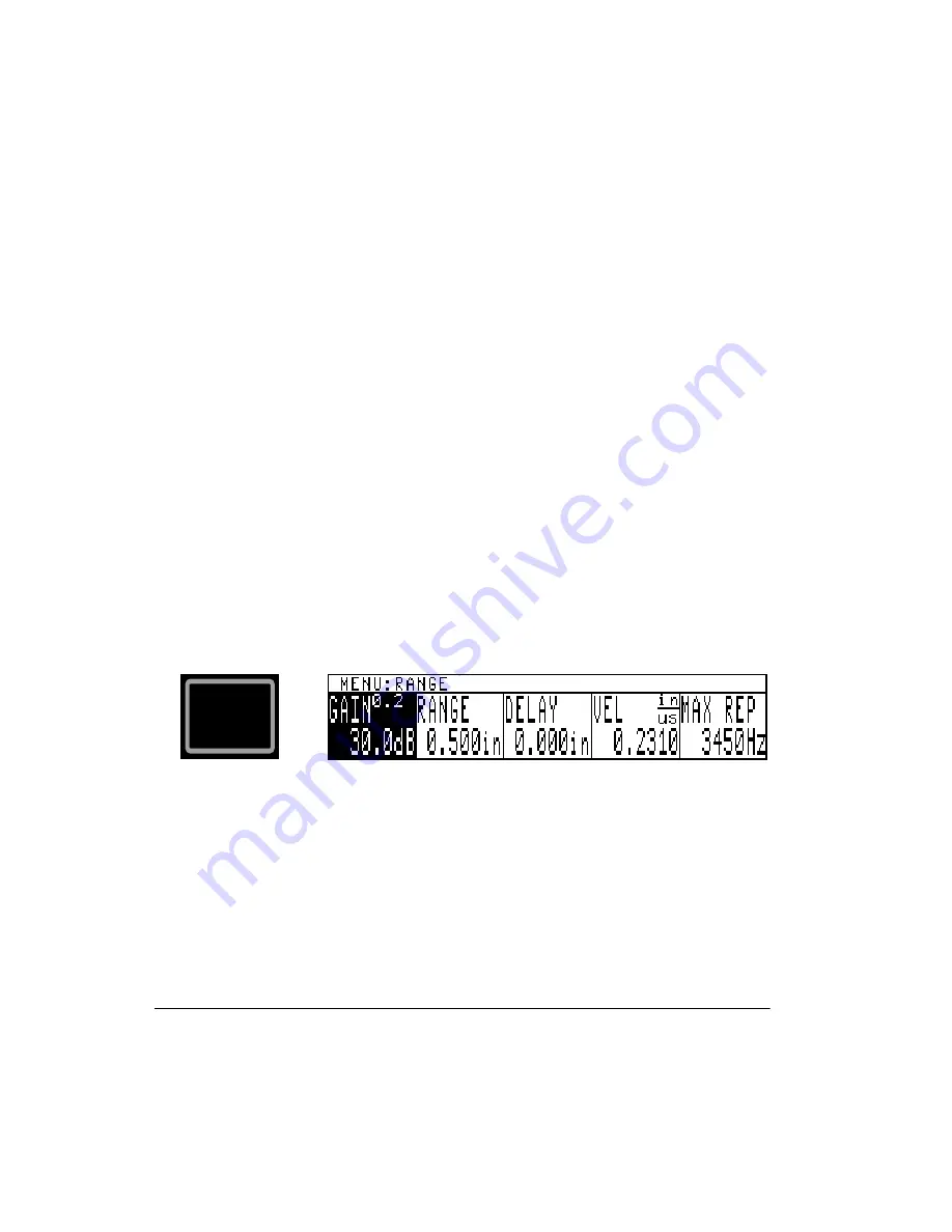
The RANGE key calls up the range menu shown and is used to adjust the time base
parameters. 

GAIN

 See GAIN parameter description in the Receiver menu section.

RANGE

 Adjusts the time base range from 0.048 to 296 inches in steel. Adjustment step size

varies from 0.001 to 1 unit. The range is corrected for the down and back time of the signal
when operating in PULSE ECHO mode. 

Refer to the VEL description for further Range limits.

RANGE

Summary of Contents for Sonic 1200S/HR

Page 1: ...PN 7720044 PN 7720066 March 2006 Sonic 1200S HR Ultrasonic Flaw Detector User s Manual...

Page 2: ...ics NDT and the Panametrics NDT logo are trademarks of Panametrics Inc Other product names mentioned in this document may be trademarks of their respective companies and are mentioned for identificati...

Page 3: ...STRICTLY LIMITED TO REPAIR OR REPLACEMENT OF A DEFECTIVE UNIT AT ITS OPTION Olympus NDT does not warrant the Sonic 1200S HR to be suitable of intended use or fitness for any particular application or...

Page 4: ...and of fitness for any particular application Olympus NDT reserves the right to modify all products without incurring the responsibility for modifying previously manufactured products Olympus NDT doe...

Page 5: ...irements 12 1 7 Ni MH Battery Characteristics 14 1 8 Li Ion Battery Characteristics 15 1 9 Charging the Ni MH Li Ion Battery 16 1 10 Operating Environment 20 2 Technical Data 21 3 FastBreak Operation...

Page 6: ...Attribute Sub Menu 58 4 26 Data Sub Menu 59 4 27 New Block Editor 60 4 28 Block Review Sub Menu 61 4 29 Text Editor 62 4 30 Instrument Reset 63 5 Applications 65 5 1 Pulse Echo Contact Thickness Testi...

Page 7: ...Block 124 6 9 Deleting All Blocks 124 7 Computer Interface 127 7 1 Description 127 7 2 RS 232 Communication 128 7 3 Modes of Operation 130 7 4 Command Strings 130 7 5 Status Reporting 131 7 6 RS 232...

Page 8: ......

Page 9: ...rements 1 5 Ni MH Battery Characteristics 1 6 Li Ion Battery Characteristics 1 7 Charging the Ni MH Li Ion Battery 1 8 Operating Environment Introduction to PowerLink The PowerLink feature enables the...

Page 10: ...nd recall features of the instrument This makes stored programs associated with transducers look the same to the operator as other stored programs Before any stored transducer programs can be recalled...

Page 11: ...hich is to be stored recalled or erased Rotating the SmartKnob will cycle through the storage locations associated with the identified transducer If no stored locations are associated with the identif...

Page 12: ...am transducer the operator will be returned to the RCVR menu on exit from PowerLink 1 1 Unpacking the Sonic 1200S HR All cartons should be opened and inspected upon receipt The cartons and contents sh...

Page 13: ...Preparation for Operation 5 1 2 Sonic 1200S HR Packages 1 2 1 Sonic 1200S Packages...

Page 14: ...6 Chapter 1...

Page 15: ...Preparation for Operation 7 1 2 2 Sonic 1200HR Packages...

Page 16: ...8 Chapter 1 1 3 Sonic 1200S HR Packages 1 3 1 Sonic 1200S Packages...

Page 17: ...Preparation for Operation 9...

Page 18: ...10 Chapter 1 1 3 2 Sonic 1200HR Packages...

Page 19: ...est should be Hands free Chest Harness Battery Belt This accessory is designed to hold the weight of the Sonic Nortec BondMaster 1200 series of nondestructive test NDT equipment and it s accessories S...

Page 20: ...ently accessed by loosening the two quick release screws and removing the battery cover Figure 1 1 Battery Cover Locations The batteries provided with the Sonic 1200S HR instrument are small lightweig...

Page 21: ...ore obtaining optimum performance It is best to charge the battery at room temperature ranging between 59 F 15 C and 86 F 30 C It is normal for the battery to become warm during charging or after use...

Page 22: ...cadmium no disposal problems Size L x W x H 8 5 x 2 1 x 0 7 in 215 x 53 x 19 mm Weight 18 4 oz 515 g Nominal Voltage 10 8V Rated capacity 3 8 Ah nominal Hours of Operation 10 hours with EL display or...

Page 23: ...s Long cycle life up to 300 charge discharge cycles Temperature Range charging 32 F to 104 F 0 C to 40 C Temperature Range operating 4 F to 140 F 20 C to 60 C Temperature Range storage 4 F to 122 F 20...

Page 24: ...re equipped with a circuit that shuts off power prior to full discharge Battery life is affected by number of charge discharge cycles storage conditions temperature and use Batteries stored for extend...

Page 25: ...e Li Ion battery Charges at approximately 1 5 ampere rate A 6 6 AH battery charges in approximately 6 to 8 hours Temperature range Batteries should be charged between 40 to 100 F 4 to 38 C for best re...

Page 26: ...em fresh 30 to 60 day intervals are recommended 5 Lithium Ion batteries The red charging indicator will light indicating that the batteries are charging The indicator will turn green when the battery...

Page 27: ...er is designed to work with Olympus NDT equipment only 1 9 5 Battery Characteristics Most batteries will not deliver their full charge on first use or after extended storage Use them until the instrum...

Page 28: ...i r c s e D t r a P r e b m u N t r a P C B U r e g r a h C y r e t t a B l a s r e v i n U 3 5 1 2 2 5 9 y r e t t a b n o I i L s t n e m u r t s n i y r e t t a b e l g n i s r o f e l b a c r o t...

Page 29: ...s damping 200 ohms 20 ns damping 50 ohms Damping Selectable 25 50 or 200 ohms Modes Selectable single dual or through transmission Receiver Frequency Band 0 3 to 20 MHz 3 dB nominal Gain 0 to100 dB in...

Page 30: ...ess RF Thickness measure on live and frozen RF display modes DAC Segmented with 25 operator selected points segments generated automatically Range 40dB total of gain and DAC limited to 110dB maximum A...

Page 31: ...ectable positive or negative occurrence Indicator Switchable horn and flashing display indicators Peak Detector Amplitude Peak amplitude of gated signal in percent of screen height Accuracy 1 Analog O...

Page 32: ...greater than 1 00 inch Distance Output Amplitude Scalable 1000mV to 4000mV Accuracy Greater of 30mV or 2 of display indication with a 1000 ohm load Modes Selectable Start to echo echo to echo autocal...

Page 33: ...tored for future playback or printout Control Resolution Selection of 3 or 4 digit control Zoom Expands gated region under Gate 1 to full display Additional Features Program Storage Provides the abili...

Page 34: ...320 H x 240 v pixel display resolution 72 Hz refresh rate Display LCD Monochrome LCD liquid crystal display 3 0 x 3 8 4 8 diagonal 320 H x 240 V pixel 72 Hz refresh rate Backlight is adjustable for di...

Page 35: ...Technical Data 27 Operating Time 8 to 10 hours typical at 75 F The estimated operating time remaining is indicated by an icon on the status display...

Page 36: ...28 Chapter 2...

Page 37: ...ction and thickness testing Angle Beam Weld Inspection and Dual Element Thickness Measurement Specific examples are given for 10 0 angle beam and 0 500 thickness measurements If your particular applic...

Page 38: ...DIFF DISPLAY FREQ REJECT PULSER RCVR GAIN TRIG ANGLE THICK O DIAM ANGLE GAIN T GAUGE TRIGGER OFFSET THKCAL T VEL THICK GAIN SCALE OFFSET SPCL GAIN GATE 1 POSN WIDTH LEVEL GATE 1 GAIN RANGE DELAY VEL...

Page 39: ...on the calibration block b Adjust the timebase DELAY until the first echo falls on the graticule line outlined for the block in use c Adjust the timebase VELocity until the second display echo falls o...

Page 40: ...sitivity using a calibrated reference block 2 Adjust the RCVR GAIN in accordance with the inspection code The weld may now be inspected using the scanning pattern indicated by code Flaw location and s...

Page 41: ...and checks until both test values read correctly The test piece may now be inspected The multi echo mode may be used by selecting the THICK T GAUGE E E mode and repeating the above procedure with GATE...

Page 42: ...ock Please keep in mind that Cal Pt 1 Cal Pt 2 OR Cal Pt 1 Cal Pt 2 Calibration is complete The test piece may now be inspected The multi echo mode may be used by selecting the THICK T GAUGE E E mode...

Page 43: ...5 NC DEC Arrow Keys 4 6 Main Menu Keys 4 7 Enter Key 4 8 Print Key 4 9 SmartKnob 4 10 RCV and XMIT BNCs 4 11 Pulser Menu 4 12 Receiver Menu 4 13 Range Menu 4 14 Gate 1 Menu 4 15 Gate 2 Menu 4 16 Thic...

Page 44: ...tribute Sub Menu 4 26 Data Sub Menu 4 27 New Block Editor 4 28 Block Review Sub Menu 4 29 Text Editor 4 30 Instrument Reset 4 1 Instrument Controls This section covers the operational controls of the...

Page 45: ...roprocessor determines the instrument configuration performs power up diagnostics and calibration and readies the instrument for operation The instrument will normally attempt to restore its last conf...

Page 46: ...e 15 pin D connector This will result in a damaged instrument and or VGA monitor Signal Display Signal Display is used to display the ultrasonic signal return from the transducer It contains a 10 divi...

Page 47: ...connecting or disconnecting the Universal Battery Charger This is normal operation s u t a t S s r o t a c i d n I n o i t i d n o C u n e M K C O L K C O L d n a N I A G g n i d u l c x e s r e t e...

Page 48: ...MAIN keys are all used to select menus The parameter to be adjusted or selected is shown in inverse video above one of the five soft keys The microprocessor keeps track of which parameter was last adj...

Page 49: ...Q REJECT PULSER RCVR GAIN TRIG ANGLE THICK O DIAM ANGLE GAIN T GAUGE TRIGGER OFFSET THKCAL T VEL THICK GAIN SCALE OFFSET SPCL GAIN GATE 1 POSN WIDTH LEVEL GATE 1 GAIN RANGE DELAY VEL MAX REP RANGE GAI...

Page 50: ...s also used to select characters in the edit function for the programmable report form In some instances the SmartKnob may be used to respond to various prompts 4 10 RCV and XMIT BNCs The two transduc...

Page 51: ...crystal is connected to a fixed 100 ohm load and the damping load is electrically connected to the transmit BNC only MODE Selectable between SINGLE DUAL and THRU XMIT modes In SINGLE and DUAL modes th...

Page 52: ...FILTR3 Filters are only accessible with software revision R00A or greater FREQ Selects the frequency of operation of the receiver filtering circuitry Selections are 1MHz 2 25 MHz 5 MHz 10 MHz 15 MHz H...

Page 53: ...ition width and level for flaw gate 1 Gate 1 may also be used for thickness measurement by enabling the T GAUGE control GAIN See GAIN parameter description in the Receiver menu section GATE 1 Selectio...

Page 54: ...e is below the threshold level OFF turns off the flaw gate If a gate is in the alarm state when the thickness gauge is OFF the amplitude is displayed under the associated gate bar in inverse video POS...

Page 55: ...s flaw gate s IP 1st thickness measurements require gate 1 while Echo Echo thickness measurements require both gates 1 and 2 Turning the thickness gauge ON forces the appropriate gate or gates ON Con...

Page 56: ...RM When the thickness gauge is turned off the thickness alarm is set to OFF Default is OFF ALARM LO Default is 0 0 inch The low alarm cannot be set for a larger value than the high alarm ALARM HI Defa...

Page 57: ...may be turned OFF for flat objects Refer to the T VEL description for further O DIAM limits 4 18 DAC Menu The DAC key activates the DAC menu This menu offers controls that allow the operator to constr...

Page 58: ...s the operator to expand the contents of the gate 1 region to full screen width Toggle ZOOM off and on for the desired display T STORE With this parameter highlighted repeated presses of the T STORE s...

Page 59: ...e following sections CONTRAST Adjusts the contrast for the Monochrome LCD display If the ambient temperature causes the LCD to become invisible this adjustment can be reached on power up by simply pre...

Page 60: ...w or filled A Scan display PROGRAM Program storage and retrieval sub menu REPORT Report form editor sub menu BAUD Used to set the baud rate for the RS 232 serial port selections If the printer does no...

Page 61: ...Thickness data logger sub menu BLOCK Selects the measurement block number T STORE Selects the next storage location for a thickness reading VALUE Displays a stored value or empty status for the curren...

Page 62: ...the selected program location If the selected location is full this control allows the operator to recall the stored program If the location is empty the operator is permitted to store the program Wh...

Page 63: ...the report form The report consists of a header seven fields and associated labels and three report entries Each of these items is programmable by the user ITEM This line displays the report item cur...

Page 64: ...while the system time is expressed in HH MM format MONTH Sets the system clock month i e 1 January 2 February etc DAY Sets the system clock to the day of the month days 1 through 31 YEAR Sets the las...

Page 65: ...e its empty status or name and time stamp RECALL A Scan images may be recalled from the selected A Scan location to the instrument screen for review Only full A Scan locations may be recalled To resum...

Page 66: ...table above indicates the attribute of the A Scan location r read only e extension of previous location Setting the attribute of A Scan locations protects these locations from accidentally being erase...

Page 67: ...erator performs an operation by pressing ENTER or the appropriate soft key BLOCK Selects the block number to be REVIEWed NAMEd DESCRIBEd DELETEd or PRINTed All blocks will be listed by name in the top...

Page 68: ...printer option to make a hard copy report of data contained in the selected block 4 27 New Block Editor The new block editor is used to establish the storage requirements for a newly created data bloc...

Page 69: ...he new data block DESCRIBE The describe function allows the operator to enter an alphanumeric block description of up to 26 characters 4 28 Block Review Sub Menu The block review sub menu is used to r...

Page 70: ...ing s from the selected location s Operator confirmation ENTER is required to complete the clear operation This operation will leave the selected location empty Note that this operation is irreversibl...

Page 71: ...operation The default parameters are listed in the following charts r e s l u P r e v i e c e R e g n a R E S L U P s n 0 0 1 N I A G 2 0 B d 0 3 E G N A R n i 0 0 1 G N I P M A D 0 0 2 Y A L P S I D...

Page 72: ...64 Chapter 4...

Page 73: ...s gauge offsets and sound velocity must be recalibrated each time the instrument is powered up The following accessories are required for this setup procedure STEP BLOCK Sonic 1920105 00 Steel Step Bl...

Page 74: ...ness Range Steel 1 Connect the transducer cable to the Spectrum E8L transducer and then to either BNC connector 2 Turn on instrument power and adjust the operating controls as follows 3 Place X30S cou...

Page 75: ...ssing the RANGE menu key the VEL menu soft key and rotate the SmartKnob to line up the leading edge of the first echo on the last graticule line refer to Figure 5 2 8 Repeat steps 3 8 to verify that b...

Page 76: ...ted for 10 inches of aluminum at full screen range with each major graticule division equal to 1 inch Different materials have different velocity attenuation and noise characteristics The best accurac...

Page 77: ...n thickness available For example using only a 1 inch steel block B1 Block calibration of 1 to 10 inches or more can be performed In highly attenuative materials that is cast materials it may not be p...

Page 78: ...choes should then line up with a graticule line as shown in Figure 5 3 If they do the instrument is calibrated for 1 0 to 10 0 inches If not repeat calibration Figure 5 3 Multiple Echoes From 1 0 Bloc...

Page 79: ...ne 4 Adjust Gain by pressing the GAIN menu soft key and rotate the SmartKnob to increase the first echo amplitude to approximately 80 of full screen height see Figure 5 4 5 Move the transducer to the...

Page 80: ...t Back Wall Reflection Press the GATE1 menu key and the following menu will appear This menu provides changeable parameters such as Polarity Position Width and Level for either flaw or thickness measu...

Page 81: ...of the thickest step 0 500 inch Figure 5 6 Echo From 0 100 Step and Figure 5 7 Echo From 0 500 Step 5 Press the THICK menu key then the T GAUGE softkey and the following menu will display 6 Use the Sm...

Page 82: ...hey can also be used on smooth materials to more than 10 inches The following accessories are required for this setup procedure STEP BLOCK Sonic 1920105 00 steel step block or equal 0 100 to 0 500 inc...

Page 83: ...ne up the leading edge of the first echo on the 2 graticule line 8 Adjust Gain by pressing the GAIN menu soft key and rotate the SmartKnob to increase the first echo amplitude to approximately 70 of f...

Page 84: ...rument Calibration 1 0 to 10 0 Inches of Steel Use the same procedure as the previous 0 100 to 0 500 inch steel test but adjust the controls using 1 to 10 inch steel step blocks as the thin and thick...

Page 85: ...ith practice you may optimize the displayed ultrasonic signals by using the Gain Damping Display Frequency and Reject control settings The Reject setting can be used to improve the display by eliminat...

Page 86: ...o both BNC connectors 2 Turn on instrument power and adjust the operating controls as follows To select and change the following parameters press the menu soft key below the selected menu box then rot...

Page 87: ...is rougher or curved you will need to adjust the Gain to acquire signals back up to about 70 Rough outer surfaces will also cause echoes after the initial pulse which restricts the resolution of thin...

Page 88: ...of Gate1 For thickness measurements adjust the controls as follows 1 To enable Gate1 press GATE1 menu key again and rotate the SmartKnob to select the Gate1 alarm 2 Press the Gate LEVEL menu soft key...

Page 89: ...ak or leading edge triggering for thickness measurements Select EDGE 7 Place the transducer on the thickest step 0 500 inch of steel press the THK CAL softkey and rotate the SmartKnob until the THK CA...

Page 90: ...d for thickness measurements Gate 1 position start must be to the left of the thinnest step echo for thickness measurements The width must be wide enough to cover the area where the 1st back wall echo...

Page 91: ...GATE1 menu key again and rotate the SmartKnob to select the Gate1 alarm 2 Press the Gate LEVEL menu soft key and rotate the SmartKnob to the desired screen height such as 35 3 Press the Gate POSN men...

Page 92: ...ate2 For this application Gate2 is used for thickness 1 To enable Gate2 press the GATE2 menu key again and rotate the SmartKnob to select the Gate2 alarm 2 Press the Gate LEVEL menu soft key and rotat...

Page 93: ...500 inch the Gate 2 position start and width must be adjusted for the thinnest echo to echo measurement such as 0 200 inch see Figure 5 18 6 Gate 2 must start prior to the 2nd back wall echo left side...

Page 94: ...per Gate1 and Gate2 positioning as above a slight adjustment of the Gate2 position may be required to prevent triggering on unwanted signals press the THK CAL softkey and rotate the SmartKnob until th...

Page 95: ...d adjust OFFSET for the block value 3 Place the transducer on the thick block and adjust the THICK VELOCITY for that value 4 Repeat as necessary 5 3 Delay Line Thickness Testing In testing thin materi...

Page 96: ...ck or equal 0 100 0 200 0 300 0 400 0 500 inch steps TRANSDUCER A 10 MHz highly damped delay line transducer is usually the best choice but a 5 MHz transducer may be used if the material is above 0 05...

Page 97: ...he DISPLAY menu soft key and rotate the SmartKnob to select HALF Observe the signals and select or depending upon best signal display 5 Adjust Delay by pressing the RANGE menu key then the DELAY menu...

Page 98: ...sducer to the thickest 0 500 step Adjust the Velocity by pressing the RANGE menu key the VEL menu soft key and rotating the SmartKnob to line up the leading edge of the first echo on the last graticul...

Page 99: ...strument Calibration Testing When using the delay line method the best results are obtained only when several multiples or echoes are displayed In some attenuative materials or plastics only one back...

Page 100: ...t step 0 500 inch Please refer to Figure 5 25 Figures 24 and 25 5 Press the THICK menu key and the following menu will display Press the T GAUGE menu soft key and use the UP DOWN arrow keys to toggle...

Page 101: ...s From the 1st Back Wall to 2nd Back Wall Reflection Echo to Echo Adjust the operating controls as follows To measure between echoes both Gate 1 and Gate 2 are used for thickness measurements Gate 1 p...

Page 102: ...rements adjust the controls as follows 1 To enable Gate1 press GATE1 menu key again and rotate the SmartKnob to select the Gate1 alarm 2 Press the Gate LEVEL menu soft key and rotate the SmartKnob to...

Page 103: ...thickest step in the calibration process 5 Press the GATE2 menu key and the following menu will appear This menu provides changeable parameters such as Polarity Position Width and Level for either fla...

Page 104: ...see Figure 5 31 Figure 5 30 and 5 31 10 Press the THICK menu key and the following menu will display Press the T GAUGE menu soft key and use the UP DOWN arrow keys to toggle through the selections se...

Page 105: ...ed signals press the THK CAL softkey and rotate the SmartKnob until the THK CAL value for CAL PT2 reads 0 400 inch Press ENTER to log this value Please refer to Figure 5 33 13 Calibration is now done...

Page 106: ...s to obtain the best results on a particular weld The following accessories are required for this setup procedure TRANSDUCER A 2 25 MHz transducer with Lucite wedge is usually used such as the Spectru...

Page 107: ...3 Place couplant on the top surface of the test block at the index point matching the wedge angle 4 Place transducer on a calibration block at the index point Refer to Figure 5 34 and Figure 5 35 for...

Page 108: ...Delay by pressing the RANGE menu key then the DELAY menu soft key and rotate the SmartKnob or press the UP DOWN arrow keys so that the first echo lines up as follows for the three test blocks IIW Typ...

Page 109: ...Figure 5 37 IIW Type 2 Line 4 4 inch See second echo in Figure 5 38 B1 Line 4 4 inch See echo pattern in Figure 5 39 8 Repeat steps 6 and 7 until both signals fall on the correct graticule lines Examp...

Page 110: ...102 Chapter 5 Figure 5 37 IIW Type 1 Block Echoes Figure 5 38 IIW Type 2 Block Echoes...

Page 111: ...first necessary to determine it To find the true index point on the wedge 11 Place the transducer with couplant on the block to reflect from the large 4 inch radius end as shown in Figure 5 40 12 Mov...

Page 112: ...ermination of angles between 35 and 75 possible The exact angle of refraction can be read at the wedge index when the echo is at its maximum height When measuring angles of refraction between 75 and 8...

Page 113: ...arks on the block Use the other side for above 60 Figure 5 41 IIW Block Refraction Angle Calibration b B1 Block Refraction Angle Transducer Locations For the B1 Block use the reflection from the side...

Page 114: ...tting the reference level Set the echo signal level according to the specific code requirement For example use the 0 062 side drill as shown in Figure 5 43 The echo should be set to vertical line 5 to...

Page 115: ...sine trigonometry can be used Direct Reflection Location of Flaws 1 Distance sound path as measured on EL LCD times the sine of the wedge angle Dist S sin angle 2 Depth sound path as measured on the E...

Page 116: ...depth calculation will give a result greater than the actual thickness as shown in Figure 5 45 Figure 5 45 Multiple Bounce Shear Calibration 1 actual depth w wall thickness 2 calculated depth s sound...

Page 117: ...tion 2 Press the GATE1 menu key GATE1 menu soft key and press the UP DOWN arrow keys or rotate the SmartKnob until the is selected 3 Press the LEVEL menu soft key and adjust the level to the desired s...

Page 118: ...triggering normally the leading edge is chosen d Place the transducer on the calibration block and peak out the thickest farthest echo by swiveling the transducer Press the THK CAL softkey and rotate...

Page 119: ...Applications 111 f Calibration is now done see Figure 5 50 Figure 5 48 Figure 5 49...

Page 120: ...ickness of the part to be inspected By entering the part thickness the DEPTH of the reflector will always be measured from the surface of the part no matter what leg or V path you are in j If the insp...

Page 121: ...range of the test part For setup purposes the screen display is for multiple echoes see Figure 5 51 5 5 1 DAC CURVONLY 1 Press the CURSOR menu soft key a small circle will appear on the display that s...

Page 122: ...he UP DOWN arrow keys or SmartKnob adjust the cursor to the next point echo 6 Press the SELECT menu soft key this will log the next point echo of the DAC Curve 7 Press the CURSOR menu soft key and wit...

Page 123: ...LECT will automatically change to ADJUST With the UP DOWN arrow keys or SmartKnob adjust the gain to increase the echo amplitude to the desired height for example from 70 FSH full screen height to 80...

Page 124: ...116 Chapter 5 Figure 5 56 59 5 Press the CURSOR menu soft key and with the UP DOWN arrow keys or SmartKnob adjust the cursor to the next point echo see Figure 5 60...

Page 125: ...to ADJUST With the UP DOWN arrow keys or SmartKnob adjust the gain to increase the echo amplitude to the desired height for example from 60 FSH to 80 FSH 7 Continue following the above steps for all...

Page 126: ...d points echoes see Figure 5 63 3 If the points echoes are adjusted to the correct amplitude the DAC CURVE is complete If the points echoes are not at the correct amplitude you may go back to the poin...

Page 127: ...enu A built in report format outputs a selected block or blocks or the entire Data Logger memory to a PC or compatible printer As with instrument control settings stored readings are retained in memor...

Page 128: ...number of data blocks and their size is dependent upon the number of available Data Logger storage locations The data logger offers up to 5 000 thickness readings Use the following procedure to create...

Page 129: ...d in the Data Logger one of the data blocks created using the procedure in the preceding section must be selected to receive the data When a new block is created it automatically becomes the current b...

Page 130: ...d in memory is displayed in one of three ways EMPTY No measurement has been stored X XXX in XX X mm The value presently stored in the displayed location number Stored readings are always displayed in...

Page 131: ...TER 2 Select the desired storage location either by the location number or by row and column 3 Select the CLEAR function using the CLEAR menu soft key 4 Press the ENTER key to confirm the clear locati...

Page 132: ...rsonal computer prior to deleting To delete a Data Logger block 1 Display the Data sub menu SPCL DATA sub menu ENTER 2 Press BLOCK menu soft key 3 Adjust the block number until the desired number is d...

Page 133: ...A sub menu ENTER 2 Press BLOCK menu soft key 3 Decrease the block number below 1 until the word ALL appears 4 Press the DELETE menu soft key 5 Press the ENTER key to confirm the delete operation any o...

Page 134: ...126 Chapter 6...

Page 135: ...r terminal The RS 232C communication port allows an external device to send commands to or obtain information from the Sonic 1200S HR With the exception of a few controls all operations available from...

Page 136: ...nnect directly to an industry standard IBM AT compatible serial port Pinouts are listed below 1 Not connected 2 Output TXD transmitted data 3 Input RXD received data 4 Input CTS clear to send 5 Signal...

Page 137: ...d the thickness gauge Separate digital and analog ground pins and a pulse for synchronizing to the pulser are also provided Alarm signals should be referenced to digital grounds and peak signal and di...

Page 138: ...characters are not echoed back All responses are terminated by a carriage return only Prompts are only returned in the event of error conditions such as the following PromptDescription C Invalid Comma...

Page 139: ...e detected the desired operation is executed Upon completion of error checking or command execution the Sonic 1200S reports back to the host terminal with a prompt The prompts vary with the RS 232 mod...

Page 140: ...arameter are listed in the following tables n o i t c n u F X W R e d o C e g n a R n o i t p i r c s e D h t d i W e s l u P W R L U P s n 0 0 0 1 0 3 n o i s r e v r a l u g e R s n 0 0 5 5 1 n o i...

Page 141: ...t a G W R 2 V L 0 0 1 5 l e v e l m r a l a 2 e t a G 2 e t a G n o i t i s o P W R 2 S P n i 5 8 1 6 1 1 m m 4 9 6 4 0 9 2 n o s d n e p e d n o i t i s o p t r a t s 2 e t a G y t i c o l e v h t d...

Page 142: ...h t t r a p m a e b e l g n A y t i c o l e v s s e n k c i h t r e t u O r e t e m a i D W R A I D n i 5 8 1 F F O m m 4 9 6 4 F F O r e t e m a i d e c a f r u s d e v r u C e c a f r u s t a l f F...

Page 143: ...o f y r a n i b m a r g o r p d e r o t s d a o l p U m a r g o r P d a o l n w o D W N D P 0 0 1 1 t a m r o f y r a n i b m a r g o r p d a o l n w o D s u t a t S n a c S W F E S 0 0 1 1 s u t a t...

Page 144: ...a l t r o p e r a d a e R t r o p e R t e S l e b a L W B L S 7 1 s r e t c a r a h c 6 2 l e b a l t r o p e r a e t i r W t r o p e R d a e R d l e i F W L F R 7 1 d l e i f t r o p e r a d a e R t...

Page 145: ...l c t n e m u r t s n I s e t u n i M k c o l C W R N I M 9 5 0 g n i t t e s s e t u n i m k c o l c t n e m u r t s n I h t n o M k c o l C W R N O M 2 1 1 g n i t t e s h t n o m k c o l c t n e m...

Page 146: ...i r P W R T R P N O N A C N O S P E I I X A T N E P L C P P H n o i t c e l e s r e t n i r p 2 3 2 S R e t a R d u a B W R S P B 0 0 2 9 1 0 0 4 2 0 0 4 8 3 0 0 8 4 0 0 6 7 5 0 0 6 9 g n i t t e s e...

Page 147: ...U K A N y l e t o m e r y e k w o r r a P U e h t e t u c e x E w o r r A n w o D y e K X A D K A N y l e t o m e r y e k w o r r a N W O D e h t e t u c e x E y e K r e t n E X N E K A N y l e t o m...

Page 148: ...r a e l C s e i r t n e d n a r a e l C t n e m u r t s n I X I L C A N d n a a t a D s n a c S A s m a r g o r P r a e l C t n e m u r t s n i l l A d a o L t l u a f e D X D A L A N s t l u a f e d...

Page 149: ...Computer Interface 141...

Page 150: ...was encountered the host sends the text string and waits for a prompt 3 Binary Read Upload Commands The binary upload transfer consists of a 2 byte size count SS followed by the binary data informati...

Page 151: ...r the following steps are used to download stored data a Host sends a Binary Download command b Host waits for the Sonic 1200S HR to respond with a carriage return 0D Hex or an error prompt c If no er...

Page 152: ...ogram 1 Example 6 Download to program location 2 t s o H S L B 1 C R L1 L 6 2 C R c i n o S t n e m u r t s n I C R C R t s o H R L B 1 C R c i n o S t n e m u r t s n I L1 L 6 2 C R t s o H P U P 1 C...

Page 153: ...Writing Seventh Edition Document Title Document Number Documentation Usability Ratings Please rate the usability of the document according to the following rating system 1 Poor 2 Average 3 Excellent...

Page 154: ...o the illustrations contribute to the usefulness of the document 1 2 3 Are the illustrations effectively integrated into the text 1 2 3 Layout and Design Is the layout effective for the audience and p...

Reviews: