19
IX71/IX51
2
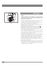
Moving the Specimen
(Fig. 17)
With the IX2-SFR or IX-SVL2 Stage
To move the specimen to a desired position, rotate the X-axis knob @
and Y-axis knob ².
}When the index mark on the upper stage is aligned with the index line ³
provided on the substages, the center of the stage center plate aperture
is almost in the center of the optical axis. Use this as a guideline when
moving the specimen.
The travel area is 50 mm (X-axis) x 50 mm (Y-axis).
}If, after observing a specimen with an objective with short WD (0.5 mm
or less), the revolving nosepiece is rotated to change the objective, the
objective may interfere with the center plate. When using objectives
with short WD or immersion objectives frequently by avoiding interference,
it is recommended to attach the optional IX-CP50 center plate with a
center aperture diameter of 50 mm.
}The travel area of the IX-SVL2 stage is 50 mm (X-axis) x 43 mm (Y-axis).
With the IX-MVR or CK40-MVR Mechanical Stage
Specimens are moved in the same manner as outlined above.
}The stage travel area is 130 mm (X-axis) x 85 mm (Y-axis) with the IX-MVR
or 120 mm (X-axis) x 78 mm (Y-axis) with the CK40-MVR.
3
Connecting the Grounding Wire
(Fig. 18)
With the IX2-SFR or IX-SVL2 Stage
}A grounding wire can be attached to the stage for electrophysiological
experiments, etc.
Prepare a grounding wire @ and one M4 screw ² and attach the
grounding wire as shown in Fig. 18.
# The screw hole may sometimes be stuck by paint, etc. In such a
case, screw in the M4 screw a few times to expose the metallic
thread inside the screw hole and improve the contact before
attaching the grounding wire firmly.
4
Adjusting the X-Axis/Y-Axis Knob Rotation Tension
(Fig. 19)
With the IX-SVL2 Stage
}The tension of the X-axis and Y-axis knobs can be adjusted independently.
1. Loosen the two setscrews @ of a knob using the provided Allen wrench,
hold the stage so that it will not move, then rotate the knob to adjust the
tension. Rotating it in the direction of the arrow increases the tension and
rotating in the opposite direction decreases the tension.
2. After adjustment, tighten the setscrews firmly.
# If the tension of a knob is too tight or too loose, skipping or returning
of image may occur during the stage movement.
Fig. 17
@
²
³
Fig. 18
@
²
Fig. 19
@

