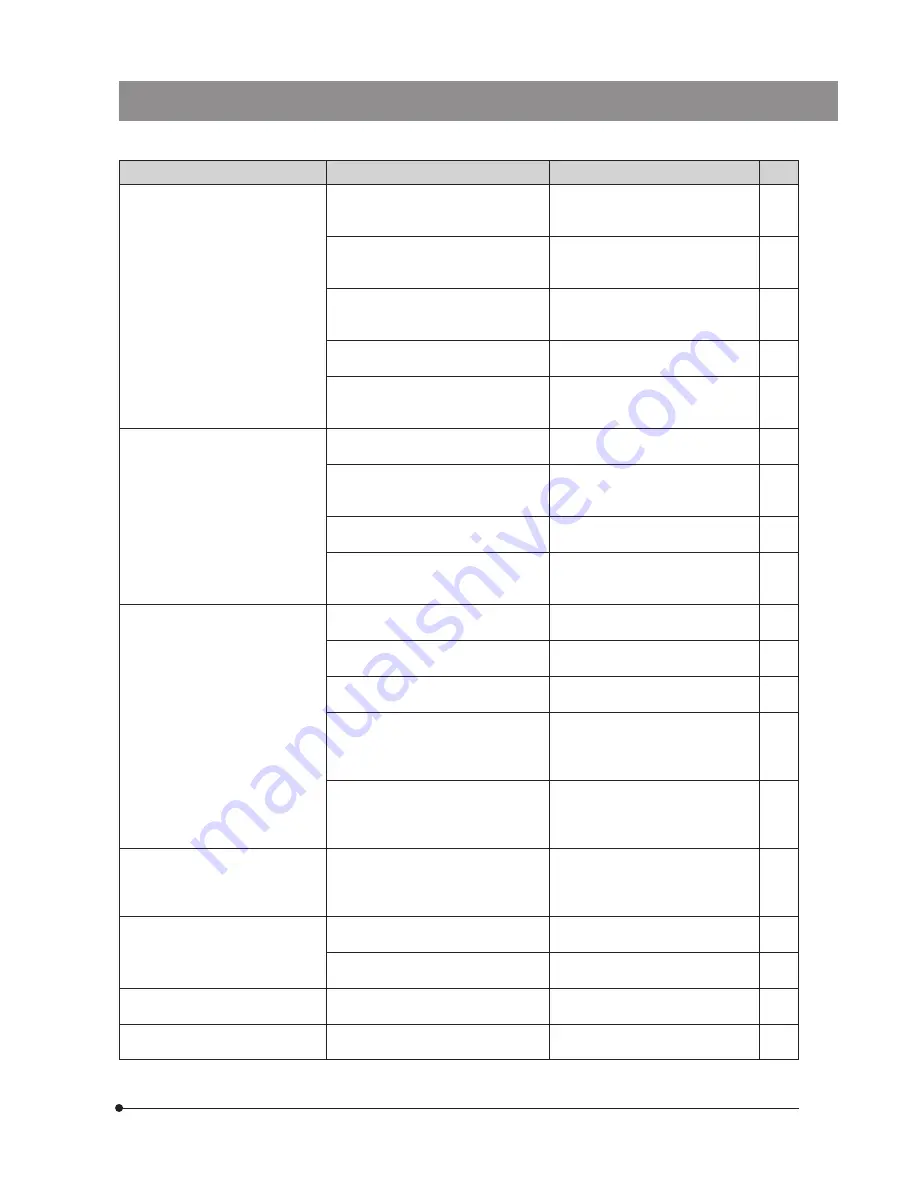
background image

DP71

24

Problem

Cause

Remedy

Page

f) Picture is too dark.

Exposure  correction is set in the -
direction.

Return the exposure correction value
to 0 and set the desired exposure
correction value.

(Online
manual)

The metering area is set to a bright area
outside the region of interest.

Move the metering area to the area
where you want to obtain optimum
exposure.

(Online
manual)

AE lock, which was set when the
exposure time was shorter than the
currently required exposure time, is active.

Cancel AE lock.

(Online
manual)

The output highlight level adjustment is
too low.

Reset the current level adjustment
and adjust the optimum level again.

(Online
manual)

The microscope illumination is too dark.

Increase the microscope illumination

intensity or disengage the existing ND
filter to increase brightness.

g) The colors in the picture are

strange.

The area selected in white balance
adjustment was improper.

Select a white area as the rectangular
white balance adjustment area.

(Online
manual)

The RGB balance is adjusted improperly
in manual white balance adjustment.

Perform manual white balance
adjustment to adjust the RGB color
balance to obtain optimum colors.

(Online
manual)

The area selected in black balance
adjustment was improper.

Select a black area as the rectangular
black balance adjustment area.

(Online
manual)

The screen color setting of the computer
is incorrect.

Set the computer display color to 24-
bit color or higher. The recommended
setting is 32-bit color.

h) The picture is not in focus.

The microscope is not focused properly.

Adjust the focus correctly with the fine
adjustment knob.

The aperture iris diaphragm of the
condenser is open too wide.

Close the aperture iris diaphragm a
little.

The field iris diaphragm is not set
properly.

Adjust the field iris diaphragm until the
image circumscribes the field of view.

Lens components of the microscope are
contaminated or the cover glass on the
front of the camera is stained.

Clean the objective, photography lens,
condenser and/or window lens of the
microscope, or clean the cover glass
on the bottom of the camera head.

5

The microscope and/or camera are
subjected to vibration during recording.

Record images in an environment in
which the microscope and camera
are not vibrated. It is effective to use
an anti-vibration bench.

i) The 4080 x 3072 and 2040 x 1536

images are not neat.

The camera is subjected to vibration
during recording.

Record images in an environment in
which the microscope and camera
are not vibrated. It is effective to use
an anti-vibration bench.

j) The DP Controller window is not

displayed correctly. Or the menu
characters are not displayed
correctly.

The resolution setting of the screen is
not correct.

Set the resolution setting at 1280 x 1024
or more in the property of the screen.

A large font has been selected in the
font size of the screen.

Select a small font in the property of
the screen.

k) External trigger signal is not

output.

External triggering is not enabled.

Enable external triggering on the DP
Controller.

(Online
manual)

l) Still image cannot be recorded

using the external trigger input.

External triggering is not enabled.

Enable external triggering on the DP
Controller.

(Online
manual)

Summary of Contents for DP71

Page 1: ...fully with the use of this camera we recommend that you study this manual thoroughly before operating the camera For image operations including recording editing and saving please refer to the Online...

Page 2: ...dance with the instruction manual may cause harmful interference to radio communications Operation of this equipment in a residential area is likely to cause harmful interference in which case the use...

Page 3: ...INSTALLATION 1 Installing the PCI Interface Board 8 2 Installing the Camera Head 9 3 Connecting the Cables 10 4 SOFTWARE INSTALLATION 5 IMAGE RECORDING PROCEDURE 6 DISPLAYED WINDOWS 7 EXTERNAL TRIGGE...

Page 4: ...e tighten firmly the lock screws on it and ensure that the connector will not slip out before setting the main switch to ON 2 The cords and cables are vulnerable to bend or twist Do not apply excessiv...

Page 5: ...operation errors and functional faults incurred due to the alteration of the environmental setup including BIOS change installation of other software or addition of hardware to the computer by the use...

Page 6: ...mpus 5 Non Olympus microscopes and commercially available C mount lenses can be used provided that they match a CCD with a size of no less than 2 3 inch and the lens projection length from the C mount...

Page 7: ...Series IBM Lenovo Think Centre Series HP dx Series xw Series 2 CPU We do not guarantee operation if the computer uses a CPU other than Pentium 4 Pentium D Pentium Extreme Edition Core2 Duo Core2 Quad...

Page 8: ...paper or clean gauze If a lens is stained with fingerprints or oil smudges wipe it with gauze slightly moistened with commercially available absolute alcohol Since the absolute alcohol is highly flam...

Page 9: ...DP71 6 1 SYSTEM CHART Note Microscopes that are not listed in the above may also be applicable For details please consult Olympus...

Page 10: ...he requirements of IEC60950 or CISPR22 24 If equipment other than these products is connected Olympus cannot guarantee any performance of the camera Connector P 10 C mount thread P 9 Tripod adapter mo...

Page 11: ...CI interface board To avoid damage due to static electricity touch an unpainted metallic surface of the computer with your hand to leak the static electricity before installation 1 Open the cover of t...

Page 12: ...If a 0 35X camera adapter is used the peripheral part of the image will be obscured Field number 22 0 63X FN 17 5 0 5X FN 22 1X FN 11 If a C mount camera adapter from other manufacturer than Olympus i...

Page 13: ...that the cable will not slip out 2 Connect the connector on the other end of the interface cable to the connector 5 on the camera head tighten the lock screws 6 on the interface cable s connector and...

Page 14: ...TWARE INSTALLATION This chapter describes the installation of the optionally available DP BSW Basic Software for DP71 Before Installation Windows is a registered trademark of Microsoft Corporation All...

Page 15: ...plication which allows you to control the DP71 for recording images and manage the images in a simplified manner using thumbnails b DP71 DP70 DP30BW TWAIN Checking this installs the program which allo...

Page 16: ...em 20 Click on the Device Manager button in the Tasks 21 When the User Account Control dialog box appears click on the Continue button 22 If the driver has been properly installed MalAd Device should...

Page 17: ...ing applications Then click on the Next button 10 The Choose Destination Location window appears If you want to change the installation destination click on the Browse button and specify the new insta...

Page 18: ...e Finish button 13 The Start Copying Files window appears When the actual installation is ready click on the Next button This starts installation of the application software 15 Take out the CD ROM 16...

Page 19: ...og box is displayed click on the Hardware tab and then click on the Device Man ager button 20 If the driver has been properly installed MalAd Device should be displayed as shown below After confirming...

Page 20: ...exposure mode Exposure mode Manual Exposure mode Manual Auto Set the exposure time SFL Auto Set the exposure time Select the metering area 30 1 or 0 1 Select the metering area 30 1 or 0 1 Perform fram...

Page 21: ...ol tab Status bar 5 6 7 8 Edit Save Window This window is sued to edit save and display images For details refer to the Online Help of the DP Manager The Online Help can be viewed by opening the Help...

Page 22: ...the trigger input the exposure start time cannot be synchronized completely For details on the time lag from the trigger input to the start of exposure see table below The trigger input is a TTL compa...

Page 23: ...se operations of the DP Controller The external trigger signal is output by starting still image recording when the shutter is closed The time lag from the trigger output to the start of exposure can...

Page 24: ...e control Exposure modes Auto SFL Auto Manual AE lock Available AE pause Available Exposure correction Correction range 2 0 EV Step 1 3 EV Metering area 30 1 0 1 The metering area is freely movable Ex...

Page 25: ...Not compatible with the x64 Edition Windows 2000 Professional SP4 English or Japanese edition Dimensions weight Camera head 112 x 75 H mm excluding projections approx 1 150 grams PCI unit 187 4 W x 12...

Page 26: ...and focusing correctly and select the camera light path The ISO speed or exposure time is set improperly Set the ISO speed exposure mode exposure time and level properly Online manual d Still images...

Page 27: ...s The microscope is not focused properly Adjust the focus correctly with the fine adjustment knob The aperture iris diaphragm of the condenser is open too wide Close the aperture iris diaphragm a litt...

Page 28: ...Add or Remove Programs window appears select OLYMPUS MICRO DP71 DP70 DP30BW under Currently installed programs and click on the Change Remove button 4 When the OLYMPUS MICRO DP71 DP70 DP30BW window ap...

Page 29: ...MEMO...

Page 30: ...MEMO...

Page 31: ......

Page 32: ...e Parkway P O Box 610 Center Valley PA 18034 0610 U S A One Corporate Drive Orangeburg NY 10962 U S A 491B River Valley Road 12 01 04 Valley Point Office Tower Singapore 248373 31 Gilby Road Mount Wav...

Reviews: