28
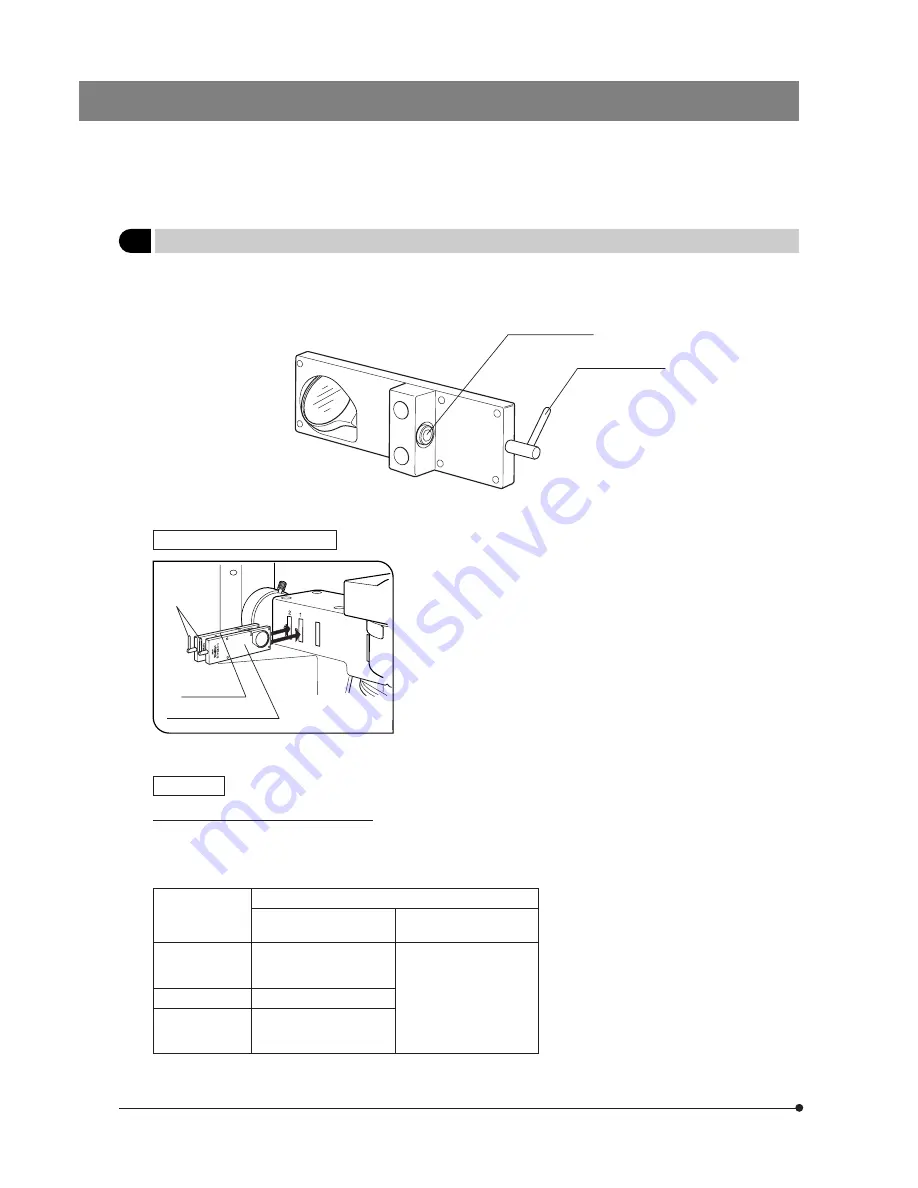
Fig. 9
4
Exciter Balancers U-EXBABG/EXBAUB/EXBAUG (for exclusive use with the BX-RFA)
}When an image of fluorescence by multiple excitation of U/B/G is observed with dual- or triple-band fluorescence mirror
units, use the exciter balancer to select the balance between the excitation light intensities of the fluorochromes.
Clamping screw
Installation Procedure (Fig. 9)
1. Stand the adjustment lever @ of the exciter balancer vertically and insert
it in one of the ND filter inlets with the same number as the slider on the
left side of the illuminator, or into the one which is located near the illumi-
nator rear panel.
· The insertion position is variable depending on the type of the exciter
balancer.
· With any type of exciter balancer, always insert so that the clamping
screw faces toward you.
2. Tighten the clamping screws using the Allen screwdriver.
Operation
Observing a Double Stained Specimen
# Due to its own characteristics, the G-exci-
tation has a narrower intensity control range
than the U- and B-excitation. The intensity
control range is also variable depending on
the status of specimen and mirror units.
# Lighting irregularities may be observed on
the upper and lower edges of the field due
to the rotation angles of filters and the vari-
ance in mirror units’ characteristics. How-
ever, these lighting irregularities does not
affect the photographed area.
1. Set up normal reflected fluorescence observation.
2. Mount the fluorescence mirror units for double staining and engage them in the light path.
}Olympus standard products
Fluorescence Mirror Unit
Exciter Balancer
Fluorescence mirror units
for double staining
Fluorescence mirror units
for triple staining
U-EXBABG
· U-DM-FI/TR2
· U-DM-FI/PI2
· U-DM-FI/TX2
· U-DM-DA/FI2
· U-DM-DA/TR2
· U-DM-DA/PI2
· U-DM-DA/TX2
· U-DM-DA/FI/TR2
· U-DM-DA/FI/PI2
· U-DM-DA/FI/TX2
U-EXBAUB
U-EXBAUG
Adjustment lever
@
U-EXBABG/EXBAUB
U-EXBAUG


