27
•
Discharge
As already explained in section ‘Operation’, ap-
proximately 80% of the stored heat is dissipated
into the room via convection through the three
channels made for this purpose.
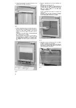
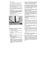
In fig.28 the front channel is shown as
’a’
, the rear
channel as
’b’
and the middle channel as
’c’
. The
air flow through the middle channel
’c’
is controlled
by the flap
’d’
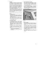
. This flap is adjusted using the left
control element
’f’
on the upper right hand side of
the heater (fig. 29a). It is continuously adjustable
from “0“ (fully counter-clockwise) to “max.“ (fully
clockwise).
This discharge control enables the heat dissipation
via the air flow through the middle channel
’c’
to be
regulated by means of naturally boosting or thrott-
ling the convection.
Fig.27 shows the flap
’d’
in the closed, fig.28 in the
open position.
Discharge can be classified in two distinct meth-
ods:
- Manual Discharge
In position “0“ (fully counter-clockwise, start of the
comet tail) the flap will not open at all, regardless
of the ambient conditions and the state of the
storage core.
If an increased heat dissipation into the room is
desired, for instance at the start of the evening,
the control mechanism must have a higher set-
ting, so that the flap can open.
- Automatic Discharge
With the control element
’f’
at setting “max.“ (see
fig.29a), the air flap opens according to the resid-
ual heat left in the storage core. If the core is still
fully charged the flap remains closed, even if the
control element is set at “max.“.
If the control element is adjusted to a certain set-
ting, the flap opens automatically as soon as the
corresponding level of heat dissipation has been
reached, e.g.:
∗
setting in middle position - the flap opens at
the beginning of the evening
∗
“max.“ setting, the flap opens early afternoon
•
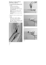
Convector heater controls
The convector is selected by an ON/OFF rocker
switch
‘g’
which illuminates when switched on “I”.
With the switch ON, the convector (direct heating)
element shall be cycled on and off by the room
thermostat
‘h’
. With the switch OFF “0” the convec-
tor will not run. The room thermostat knob is
marked 1 to 6. The higher setting number chosen,
the higher the level at which the room temperature
will be controlled.
Your comfort level can easily be established by
gradually adjusting the thermostat until the re-
quired room temperature is maintained. The con-
vector will not run if the storage heater is charged.
fig.29b
•
Commissioning
Set charge and discharge adjusters to the “max.“
position and leave them in this position for 48
hours (i.e. 2 charging cycles).
Due to manufacturing techniques, a part of the
heater insulation contains some binding agents
which can cause unpleasant odours during the first
charging. Any dust or machine oils which have col-
lected on the surface of, for instance, the heating
elements will also burn off, causing possible
odours.
It is thus vitally important that the room(s) be well
ventilated during the first 48 hours or 2 charge cy-
cles!
g
h


