background image

30 


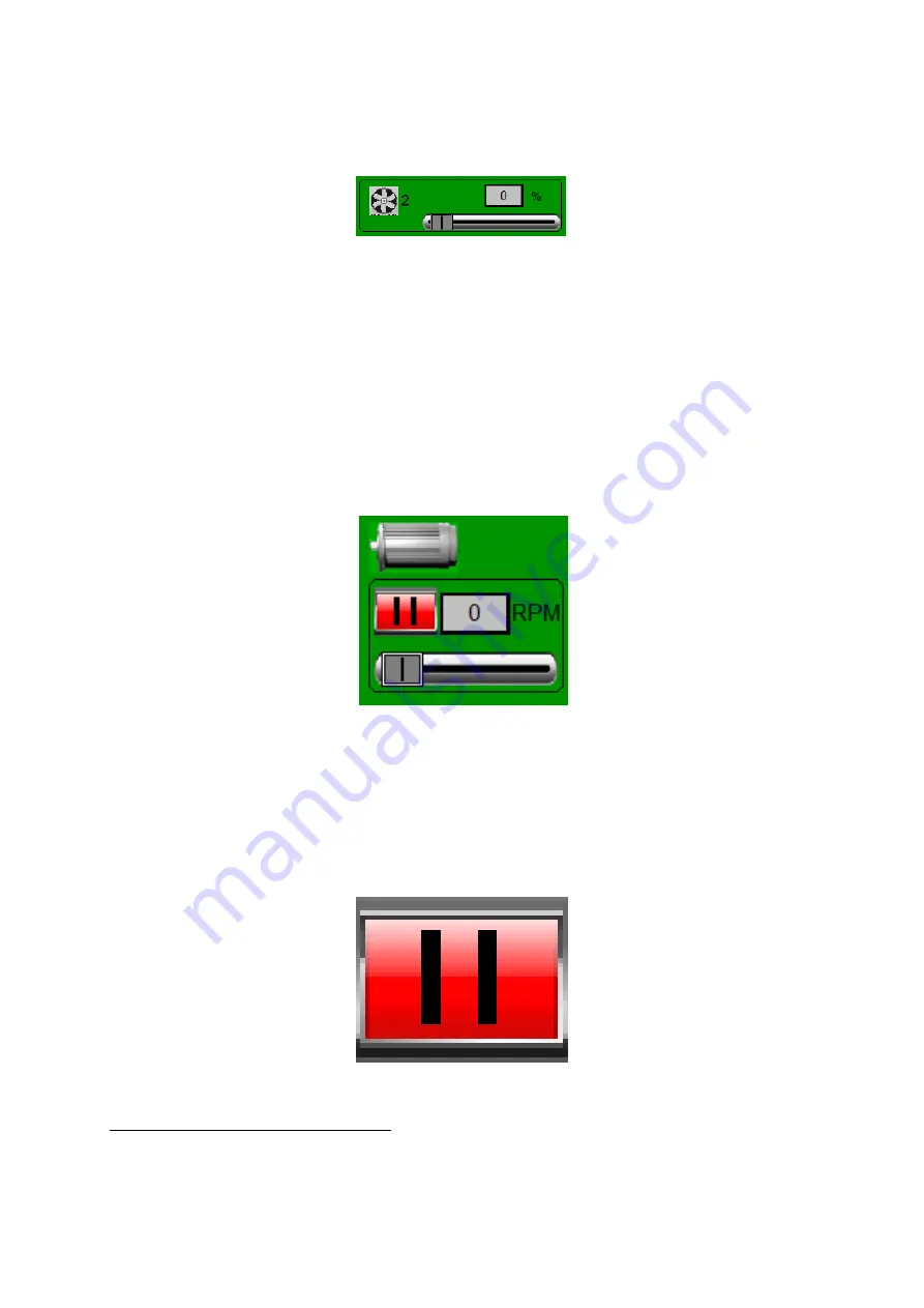
The area shown in the figure is for the airchest two sensor readouts, heater control, 

and fan controls. The fans are controlled by slider bar or grey input box at the bottom 
of the screen as shown in Figure 6.3. 


Figure 6.3:  

Fan Controls  Area 


To change the fan speed, which is in units of %, simply tap on the grey input box to 

enter an exact value into the keypad that pops up, or use the slider bar to increase or 
decrease the speed.

2


6.1.2


Deck Eccentric Controls 

The Deck Eccentric is controlled in the middle left part of the control panel screen as 
shown in Figure  6.4. 


Figure 6.4: 

Deck Controls Area 


To change the deck eccentric speed, which is in units of RPM, simply tap on the grey 

input box to enter an exact value into the keypad that pops up, or use the slider bar to 
increase or decrease the speed.

3

. The deck eccentric has another control which allows for 

the pausing or starting of the deck.  See Figure 6.5. 


Figure 6.5: 

Deck Eccentric Pause Button 


2

see Oliver’s training video entitled ”Changing the Fan Speed”


3

see Oliver’s training video entitled ”Controlling the Deck Eccentric”


Summary of Contents for DVX

Page 1: ...Fluidized Bed Dryer Automated GVX Version 1 0 1 5 23 Oliver Manufacturing Company 27151 Harris Road La Junta CO 81050 888 254 7814 olivermanufacturing com Operations manual...

Page 2: ...le Section Revision Date Main Section Introduction to Installation and Functional Operation Setting Up Machine from HMI Modes of Operation V 3 6 2020 Appendix A The PanelView Plus Appendix B CompactLo...

Page 3: ...theMachine Options 13 5 1 Fan VFDs 15 5 1 1 Fan Speed Scaling 16 5 1 2 Fan Current DC Bus Voltage and Temperature alarm limits 18 5 2 Deck Eccentric VFD 19 5 2 1 Deck Eccentric Speed Scaling 19 5 2 2...

Page 4: ...ise Cycle Timer 34 6 2 3 Deck Shake Timer 35 6 2 4 Current Timer Readouts 36 6 2 5 Differential Temp Alarm 37 6 3 Local and Remote Mode 38 6 4 Clean Out 38 6 5 Trim 39 6 6 Changing Recipes 40 7 Diagno...

Page 5: ...iv List of Tables 1 1 Model Voltages and Total Amp Draws 4...

Page 6: ...heat 17 5 10 Fan scaling Example for Dryer with heat 17 5 11 Changing Fan 1 speed command forExample 2 18 5 12 Setting output current A limits for Fan 1 18 5 13 Setting output current A limits for Fan...

Page 7: ...seconds on 10 seconds off repeated through a 30 secondbatch cycle 36 6 21 Time Remaining 37 6 22 Time Remaining Deck Off 37 6 23 Navigating to the differential temp alarm settings 37 6 24 Differential...

Page 8: ...1 Part I Installation and Functional Operation...

Page 9: ...procedure for the machine Next the functional operation and initial setup ofthe machine will be described Then the operation of themachine in its various modes willbe discussed Finally severalattached...

Page 10: ...or changing or cleaning 1 2 Handling The DVX Fluidized Bed Dryer weighs several thousand pounds depending on the model and accessories ordered with it Be sure that the handling equipment is adequate f...

Page 11: ...2 DVX616 208 230V 30 Amps 50 Amps 70 Amps 115 Amps 150 Amps 480V 20 Amps 30 Amps 50 Amps 70 Amps 80 Amps Table 1 1 Model Voltages and Total Amp Draws NOTE As of November1st 2012 the warrantycovering t...

Page 12: ...to switch the state of the water comesfromtheair andfromtheparticlesthemselves Hotter air fromthefanswill speed up the drying process because it has more heat that can be dissipated to the water incr...

Page 13: ...ry but they are also dry at the center part of the deck This means that the deck end raise can be increased moving the deck towards a flat position and a slope from the Feeder to the Discharge End c T...

Page 14: ...7 Figure 2 1 Putting particles on the deck and adjusting a Particles drying early b and drying at the end of the deck c...

Page 15: ...8 Figure 2 2 Putting particles on the deck and adjusting a Particles drying early b and drying at the end of the deck c...

Page 16: ...red settings which are then transferred to the PLC which then uses its internal programming to run the machine The PLC is like a small computer It has a processor memory inputs outputs and a small dis...

Page 17: ...10 Figure 3 2 The Human Machine Interface HMI PanelView Plus HMI Figure 3 3 The Variable Frequency Drive VFD PowerFlex 525...

Page 18: ...sting the dryer Never operate the dryer with the air filters removed Never operate the dryer with the deck removed Never operate the dryer with missing or worn parts Never operate the dryer with the a...

Page 19: ...12 Part II Setting Up the Machine from the HMI...

Page 20: ...sor options as well as the dryer options menu button used to set up the available options for the dryer 1 Figure 5 1 Menu Bar Inordertoarriveattheoptionsforthedryer theusermustbeloggedinastheengineer...

Page 21: ...er Once the user is logged in as the engineer user press the menu button marked Dryer Options on the right hand side to go to the installed options screen See Figure 5 3 Figure 5 3 Navigating to the D...

Page 22: ...FD Deck End Raise Temperature Range Gates on machines with installed End gates Figure 5 5 Dryer s installed options screen top menu buttons Additionally there are options for setting the IP addresses...

Page 23: ...or the fan speed as well as how the PLC scales the command when it sends it to the VFD Figure 5 8 shows the boxes related to setting the scaling Figure 5 8 Fan scaling options The grey boxes on the le...

Page 24: ...y be able to command it from 50 to 100 of this value then the setup would look like Figure 5 10 3 Figure 5 10 Fan scaling Example for Dryer with heat Notice that since the minimum and maximum must cor...

Page 25: ...right side one on the left Figure 5 12 Setting output current A limits for Fan 1 The grey input boxes to the right are used to indicate the full range of values the output current in amps can take on...

Page 26: ...14 Selecting the Deck VFD Options This will cause a popup window to open as shown in Figure 5 15 Figure 5 15 Deck options pop up window For the Deck Eccentric VFD there is options for setting the scal...

Page 27: ...the user can input on the control panel screen For the typical setup given above Figure 5 18 shows that the allowable input value on the control panel screen for the Deck Speed is limited to 200 to 60...

Page 28: ...zero amps Figure 5 20 Setting output current A limits for Deck Eccentric Example On the control panel the alarms are indicated on the bar graph in Diagnostic mode When theoutputcurrent or dcbusvoltag...

Page 29: ...dback coming back to the PLC Figure 5 25 Voltage Feedback Using the three areas of the screen the deck can be manipulated to the fully up and fully down endraise positions and the voltage read back fr...

Page 30: ...e airchest temperature setting for the heater in degrees F can take on The boxes on the left are used to set values for the lower and upper alarm values if needed 7 5 5 End Gate Option In some Dryers...

Page 31: ...ge input boxes The red up and down buttons will force the deck to extend and retract allowing the user to force the deck to 0 and 100 deck end raise The little triangular lights will light up when the...

Page 32: ...and Port of the PLC in the machine The default IP addresses from the factory unless otherwise specified are HMI s IP192 168 10 11 PLC s IP 192 168 10 10 Gateway 192 168 10 12 Subnet 255 255 255 0 Note...

Page 33: ...26 Part III Modes of the Machine...

Page 34: ...submodes as follows 1 Auto Mode a Continuous SubMode b Batch SubMode c Local SubMode d Remote SubMode 2 Diagnostic Mode The modes and submodes are chosen from the Control Panel screen through the use...

Page 35: ...is started at the local HMI or if it is started via the plant SCADA If it is in local mode then a start button will be on the Control Panel screen and if in remote mode there will be no start button...

Page 36: ...that have been made They are as follows 1 Fan Controls 2 Deck Eccentric Controls 3 End Raise Controls 4 Sensor Readouts 5 Heater Settings 6 Start Button 7 Dust Hood Light Button 6 1 1 Fan Controls Th...

Page 37: ...Eccentric Controls The Deck Eccentric is controlled in the middle left part of the control panel screen as shown in Figure 6 4 Figure 6 4 Deck Controls Area To change the deck eccentric speed which i...

Page 38: ...ise Controls 6 1 4 Sensor Readouts Each DVX Dryer has a temperature and humidity sensor pair in both the airchest and dusthood for each zone The number of zones is equal to the number of fan controls...

Page 39: ...Machine Off Figure 6 11 Start Button Machine On and recipe running Note When the start button is pressed all navigation to other screens is lockedout Youcan tadjustanyoptions onthemachine exceptatthe...

Page 40: ...along thedeck Thebatchmodethen utilizescontrolthroughvarioustimingoperationsrelated to a batch run Batch mode has all of the same controls as the continuous mode with the following additionalcontrols...

Page 41: ...n started This is done by turning on the machine via the start button just as one would do in continuous mode Note Thebatchtimersettings cannotbe alteredwhile abatchisrunning The timer will not reload...

Page 42: ...ing cycle all over again If the user wanted to set the time between stirs to be 5 seconds and keep the settings from the previous example then it would look like Figure 6 18 Figure 6 18 End Raise Time...

Page 43: ...conds off repeated through a 30 second batch cycle Note The deck shake timer setpoint cannot be altered while a batch is running The timer will not reload the new setting until the current batch is st...

Page 44: ...and the Dusthood Typically early in the drying process the air coming in from the airchest to the seed is much higher in temperature than the dusthood air temperature As the seed dries this temperatur...

Page 45: ...levant in both batch and continuous mode It is set by using the dial for local and remote on the Control Panel Screen 6 4 Clean Out The automatic mode has a cleanout functionality that can be accessed...

Page 46: ...ed and then restarted so the new values will load into the timer and the process starts again The bottom of the screen shows several elapsed times for various stages of the cleanout process See Figure...

Page 47: ...the button is green the trim is engaged 6 6 6 Changing Recipes The recipes are the main driving force behind the Auto Mode They are used to store settings to be used again next year or when a run need...

Page 48: ...here are two columns with values for each setting the saved recipe column and the loaded recipe column The loaded recipe column as the name infers indicates the name of the last recipe loaded as well...

Page 49: ...ecipe Setup Screen as a Supervisor Engineer user TheSupervisor hastheuseoftwomorebuttons ontheRecipeScreen theNewRecipe and the Delete Recipe buttons Todelete a recipe simply highlight the recipe that...

Page 50: ...ered into the saved recipe column press the update recipe button or to cancel hit the cancel button 7 Figure 6 33 Recipe List with a new Recipe Figure 6 34 Recipe Setup Screen with Update Recipe and C...

Page 51: ...tic Mode the user must be logged in as a Supervisor In diagnostic mode the control panel screen will look like Figure 7 1 Figure 7 1 Control Panel in Diagnostic Mode There are three additional tools t...

Page 52: ...7 2 Figure 7 2 Control Panel in Diagnostic Mode with Start Buttons Highlighted 7 2 Deck End Raise Feedback The deck end raise has a display for the voltage feedback for the deck This will allow the su...

Page 53: ...aswell asalarmconditions aresetbytheengineer whosetup theDryer These limits should not be changed unless instructed to do so The graphs themselves will display the relative value of the amperage volt...

Page 54: ......

Reviews: