30
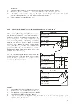
ir r m val
ir
at r ta
Off
OK
Ca c l
NOTES:
1.
This function can only be activated if the unit is switched Off. In addition, this function must be disa-
bled before the unit can be switched On.
2.
If the relative function is activated (paragraph 8.3), the value of these parameters will be stored in the
memory and automatically reset after any possible voltage failure.
7.11.
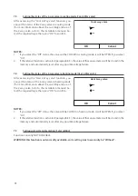
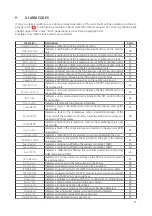
Setting the air purging function (Air removal)
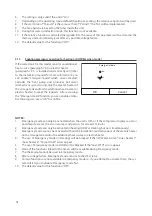
After accessing the “Air removal” function, you can
activate water circulation (in the selected circuit) to
eliminate any air from the circuit. Select the required
logic, then press “OK” to confirm.
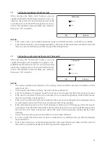
After accessing the “Floor debug” function, you can
activate or deactivate any possible procedure for
pre-heating the radiant panels. This procedure creates
a heating cycle during which the temperature is kept
stable for a certain time (period), then increased by a
value equal to
Δ
T indicated, and kept there for the next
period. This temperature increase and hold procedure
will be repeated for the number of periods specified.
At the end, press the button at the top right to start (or
interrupt) the pre-heating cycle.
NOTES:
1.
During the execution of this function, all other functions are disabled.
2.
You are advised to use this function to gradually activate the heating function via the radiant panels
(this procedure should be carried out at the start of the season).
3.
If the relative function is activated (paragraph 8.3), the value of these parameters will be stored in the
memory and automatically reset after any possible voltage failure.
Start
Floor debug: On
Segments: 2
Period 1 temp: 25°C
Segment time: 12H
T of segment: 5°C
7.12.
Setting the pre-heating procedure for radiant panels (Floor debug)
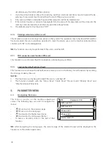
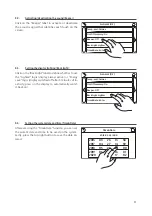
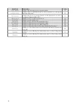
After accessing the "Manual defrost" function, you can
activate or deactivate the command for forced execu-
tion of a defrost cycle. Make your selection, then press
“OK” to confirm.
Manual defrost
On
Off
OK
Cancel
7.13.
Activating the defrost cycle (Manual defrost)
31
NOTES:
1.
This function can only be activated if the unit is switched Off.
2.
The defrosting cycle is automatically interrupted if the defrosting temperature rises above 20°C, or
in any case after 10 minutes.
3.
If the relative function is activated (paragraph 8.3), the value of these parameters will be stored in the
memory and automatically reset after any possible voltage failure.
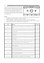
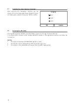
After accessing the "Force mode" function, you can ac-
tivate or deactivate the command to execute the spe-
cific heating or cooling function. Make your selection,
then press “OK” to confirm.
rc m
rc c l
rc at
Off
OK
Ca c l
NOTES:
1.
This function can only be activated if the unit is switched Off after a re-start.
2.
The unit status (On/Off) cannot be modified while this function is in progress.
3.
If the relative function is activated (paragraph 8.3), the value of these parameters will be stored in the
memory and automatically reset after any possible voltage failure.
7.14.
Activating mode forcing (Force mode)
After accessing the “Gate-Ctrl” function, you can ac-
tivate or deactivate the management of the switch-
on/switch-off command via the external contact (for
more information about this contact, refer to the in-
stallation manual). Make your selection, then press
“OK” to confirm.
Gate Ctrl.
On
Off
OK
Cancel
NB:
1.
This function must only be activated if an auxiliary device is installed; otherwise the unit will be
blocked.
2.
When this function is active, the unit will only receive operating consent when the circuit on the
dedicated terminals (for more information, refer to the installation manual) is CLOSED. The display
will show a message if you attempt to start an operation while the circuit is OPEN.
3.
If the relative function is activated (paragraph 8.3), the value of these parameters will be stored in the
memory and automatically reset after any possible voltage failure.
7.15.
Activating auxiliary device management (Gate-Ctrl)
Function currently NOT AVAILABLE.
WARNING: this function is not currently available, so its setting must necessarily be “Off”.
7.16.
Setting the intake limit (intake limit)
Summary of Contents for SHERPA MONOBLOC
Page 191: ......
Page 192: ...262617B...

