30
I
GB
F
D
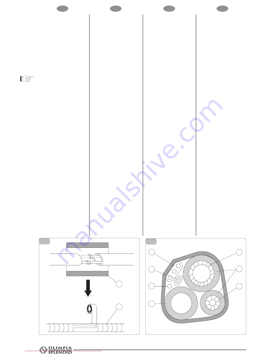
Isolamento termico delle
giunzioni delle tubazioni
- Avvolgere le giunzioni delle
tubazioni con materiale isolante
termico (fig. 10 A) e quindi
avvolgere con nastro in vinile (fig.
10 B).
Isolamento termico delle
tubazioni
1 Posizionare il tubo di drenaggio
sotto le tubazioni.
2 Il materiale isolante è costituito di
schiuma di politene di spessore
superiore ai 6 mm.
Nota: Il tubo di drenaggio
viene preparato
dall'utilizzatore.
Fig. 1
A Cavo di alimentazione
B Cavo di alimentazione 1 (per
pompa di calore)
C Cavo Sbrinamento (per pompa di
calore)
D Tubo drenaggio (preparato
dall'utilizzatore)
E Tubo grande
F Tubo isolamento termico
G Tubo piccolo
- Il tubo di drenaggio dovrebbe
essere rivolto verso il basso in
modo da facilitare il flusso di
drenaggio. Fate in modo che il tubo
di drenaggio non sia arrotolato,
sporgente o libero, non immergere
la parte terminale in acqua. Se è
collegata una prolunga di
drenaggio al tubo di drenaggio,
accertarsi che vi sia l'isolamento
termico nel passaggio lungo
l'unità interna.
Fig. 12
A Base
- Quando le tubazioni sono rivolte
verso destra, le tubazioni, il cavo
di alimentazione ed il tubo di
drenaggio dovrebbero essere
isolati termicamente e fissati al
retro dell'unità.
Calorifugeage des raccords
des tuyaux
- Entourez les raccords des tuyaux
de matériau calorifuge (fig. 10 A)
puis de ruban vinyle (fig. 10 B).
Calorifugeage des tuyaux
1 Placez le tuyau de drainage sous
la tuyauterie.
2 Le matériau isolant est constitué
de mousse de polyéthylène de
plus de 6 mm d'épaisseur.
Note: Le tuyau de drainage
est préparé par l'utilisateur.
Fig. 1
A Câble d'alimentation
B Câble d'alimentation 1 (pour
pompe à chaleur)
C Câble de dégivrage (pour pompe
à chaleur)
D Tuyau de drainage (préparé par
l'utilisateur)
E Tuyau grand
F Tuyau de calorifugeage
G Tuyau petit
- Le tuyau de drainage devrait être
dirigé vers le bas pour faciliter le
flux de drainage. Faites en sorte
que le tuyau de drainage ne soit
pas enroulé, qu'il ne dépasse pas
et qu'il ne soit pas libre, ne plongez
pas l'extrémité dans l'eau. Si une
rallonge de drainage est reliée au
tuyau de drainage, assurez-vous
que le passage le long de l'unité
intérieure est calorifugé.
Fig. 12
A Base
- Quand la tuyauterie est dirigée
vers la droite, le câble
d'alimentation et le tuyau de
drainage devraient être calorifugés
et fixés à l'arrière de l'unité.
Wärmeisolierung der
Rohrleitungs-Kupplungen
- Umwickeln Sie die Rohrleitungs-
Kupplungen mit
Wärmeisolierungsmaterial 10 A).
Umwickeln Sie anschließend mit
Vinyl-Band (Abb. 10 B).
Wärmeisolierung der
Rohrleitungen
1 Positionieren Sie das
Entwässerungsrohr unter den
Rohrleitungen.
2 Das Wärmeisolierungsmaterial
besteht aus Polythen-Schaum mit
einer Stärke von mehr als 6 mm.
Hinweis: Das
Entwässerungsrohr wird
vom Anwender vorbereitet.
Abb. 1
A Versorgungskabel
B Versorgungskabel 1 (für
Wärmepumpe)
C Abtaukabel 1 (für Wärmepumpe)
D Entwässerungsroh (vom
Anwender vorbereitet)
E Großes Rohr
F Wärmeisolierungsrohr
G Kleines Rohr
- Das Entwässerungsrohr sollte
nach unten gerichtet sein, damit
der Dränungsfluss unterstützt
wird. Achten Sie darauf, dass
das Entwässerungsrohr nicht
zusammengerollt wird, übersteht
oder freiliegt. Tauchen Sie das
Endstück nicht in Wasser.
Stellen Sie beim Anschluss einer
Entwässerungsverlängerung an
das Entwässerungsrohr sicher,
dass die Wärmeisolierung im
Durchgang entlang der
Inneneinheit vorhanden ist.
Abb. 12
A Sockel
- Wenn die Rohrleitungen nach
rechts gerichtet sind, sollten die
Rohrleitungen, das
Versorgungskabel und das
Entwässerungsrohr wärmeisoliert
und mit einer
Anschlussvorrichtung für
Rohrleitungen an der Rückseite .
Piping Joints Thermal
Insulation
- Wrap the piping joints with thermal
insulation (fig. 10 A)materials and
then wrap with a vinyl tape (fig.
10 B).
Piping Thermal Insulation:
1 Place the drain hose under the
piping.
2 Insulation material uses
polythene foam over 6mm in
thickness.
Note: Drain hose is
prepared by user.
Fig. 1
A Power cord
B Pover cord 1 (for heat-pump)
C Defrost cable (for heat-pump)
D Drain hose (prepared by user)
E Large pipe
F Thermal insulation tube
G Small pipe
- Drain pipe should point downward
for easy drain flow.
Do not arrange the drain pipe
twisted, sticking out or wave
around, do not immerse the end
of it in water.
If an extension drain hose is
connected to the drain pipe,
make sure to thermal insulated
when passing along the indoor
unit.
Fig. 12
A Base
- When the piping is directed to
the right, piping, power cord and
drain pipe should be thermal
insulated and fixed onto the back
of the unit.
11
A
B
C
D
E
F
G
A
B
10
Downloaded from AC-Manual.com Manuals


