


7
IMTP 2.2 - ITTP 2.2/4/5.5/7.5
ENG
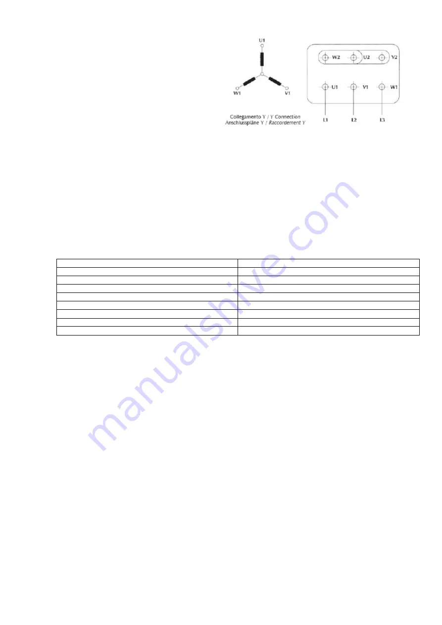
The
three-phase
inverters
ITTP2.2
and
ITTP5.5/7.5
must be installed on asynchronous
three-phase motor with 200-460 Vac 50/60 Hz
voltage supply. The phases must be connected
in star mode if the motor is 230V / 400 V
(most common case, as in Fig 4).
Figure 4 – Star motor phases connection
The unit is equipped with output over-current
protection; it is not necessary to install any
additional safety device between the inverter and the pump in order to protect the motor in case of failure.
5.5 Electric connection to Line and Motor
Supply for IMTP2.2 device is a single-phase voltage 100-240Vac, 50/60Hz.
Supply for ITTP2.2 and ITTP5.5/7.5 device is a three-phase voltage 200-460Vac, 50/60Hz.
The plant to which the inverter is connected must be conforms to safety regulations in use:
¥ Differential automatic switch: I n = 30mA recommended type A or B (specific for Inverters load)
¥ Magnetic-thermal automatic switch with intervention current proportionate to the power of
the pump installed (see Table 1)
¥ Ground connection with total resistance less than 100 ½
Pump power (kW)
Magnetic-Thermal protection (A)
0.37 (0.5 Hp)
4
0.75 (1 Hp)
6
1.5 (2 Hp)
12
2.2 (3 Hp)
16
3 (4 Hp)
20
4 (5.5 Hp)
25
5.5 (7.5 Hp)
32
7.5 (10 Hp)
40
Table 2: Magnetic-Thermal protection
To make
electrical connections
observe the following instructions (reference to Figure from 5 to 9):
·
Open the inverter box unscrewing the 4 screws on the cover;
·
Wait at least two minutes before work on the Inverter to ensure that the capacitors are fully discharges;
·
Fix the bottom of the inverter box to terminal motor case with the 4 screws;
·
If is necessary, disconnect the two cables connectors from the logic board J1 (26 poles) e J2 (4 poles) for
IMTP2.2-ITTP2.2 (Figure 5) or J5 (26 poles) for ITTP4/../ 7.5 (Figure 8);
·
Connect the 3
motor terminals
U, V, W on the power board on IMTP2.2 / ITTP2.2 /../7.5 (fig. 6, 7, 9); use
the up-level connector extension for ITTP4.0W, ITTP5.5W, ITTP7.5W;
·
Connect the
pressure transducer
terminals on the logic board (see paragraph 5.6);
·
Optional 1 -
enable contact
: If possible connect the float switches or probe level (with NC contact)
between terminals EN (enable, pole 8 of J9) and GND (common, pole 8 of J9) on the logic board of IMTP-
ITTP2.2 (figure 5) or between EN (pole 1 of J11) and C (pole 2 of J11) on the logic board of ITTP5.5/7.5
(figure 8), replacing the wire connected by the constructor;
§
Optional 2:
MASTER – SLAVE Operating Mode on RS485 serial bus
: in a group of pumps controlled by
inverters connect the two wires of RS485 at the terminal J10 of the logic board on IMTP-ITTP2.2 or on J2
of the logic board of ITTP4/../7.5, respecting the polarity A or B;
§
Optional 3: Auxiliary ON/OFF Pump contact: for IMTP2.2 and ITTP2.2 version, there is a relay output
contact (3, 4 of J11, AUX-COM, fig.5) that close when the pressure is less than the reference value and
the motor velocity arrive to the maximum velocity, then re-open when the pressure is higher than the
reference value and the flow arrive to the minimum stop value; this relay contact is 2 Ampere - 250Vac
maximum, useful to drive a contactor for a second ON-OFF pump, and work only when the control group
mode is in Pressure mode; Warning: connect only contactors or relay coils with maximum voltage of
250Vac;
For ITTP4.0/../7.5 this output is 12VDC-100mA on the poles marked with AUX and "-" on J10
(fig. 8) which can be connected to 12Vdc coil of a relay, to control a second ON / OFF pump, with the
same logic insertion and removal models described above to 2.2 kW;


