


3
IMTP 2.2 - ITTP 2.2/4/5.5/7.5
ENG
1. SPECIFICATIONS
With this manual, we would like to give you the most important information about the correct use and
maintenance of the inverter.
The devices described in this manual are:
§
IMTP2.2M-RS
: Single-phase Inverter for motor pump, max 2.2 kW (3 Hp)
§
ITTP2.2M-RS
: Three-phase Inverter for motor pump, max 2.2 kW (3 Hp)
§
ITTP4.0M/W-RS
: Three-phase Inverter for motor pump, max 4 kW (5.5 Hp)
§
ITTP5.5M/W-RS:
Three-phase Inverter for motor pump, max 5.5 kW (7.5 Hp)
§
ITTP7.5W-RS:
Three-phase Inverter for motor pump, max 7.5 kW (10 Hp)
This inverters are devices specially designed for pump motor control, thanks to a perfect feed-back pressure: it
assures a good energy saving and it has many programmable functions, that are not in the other common
directly supplied motor pumps.
The following instructions and rules about the standard configuration are as follows.
If you require technical assistance regarding specific parts at Service Sales please do specify the exact initials
of the model, followed by the serial number of the model.
2. WORKING OPERATIONS
This PumpÐInverter system is made up by a centrifugal pump, that is moved by an asynchronous motor. This
system has to keep the pressure steady, independently from the flow (consistent with the maximum load
applicable to the motor, otherwise the maximum current absorption).
The output pressure is monitored by a pressure transducer, with 4-20mA or 0-5V output. The control logic works
with an output of 5 or 15V (switchable), that supplies the pressure transducer.
MINIMUM FLOW WORKING PROTECTION: to prevent a closed delivery working, the control logic read the
motorÕs working point condition; if this point is under a setting value, the system switches off the pump, and
appears on the display ÒMinimum FlowÓ. At the end of this condition, the system restarts its normal operation.
The pump curve is detected by the initial self-regulation check.
DRY WORKING PROTECTION: To avoid that the pump can continue to operate after a problem in absence of
suction/intake water, the system read some information of the electric motor, in a time of 40 seconds, and when
they go below a minimum, turn off the pump and show the relative signal of alarm ÒDry WorkingÓ. The inverter
tries N¡5 consecutive re-start in this condition, one spaced 15 minutes of each other. After the fifth consecutive
fault, switch on the led Alarm and the re-start must be manually do, pressing STOP followed by START.
The motor pump electric protection is controlled by the limitation of the current absorption (programmable).
When the current protection is on, an alarm appears on display. When the condition disappear, the system
restart with the normal functioning.
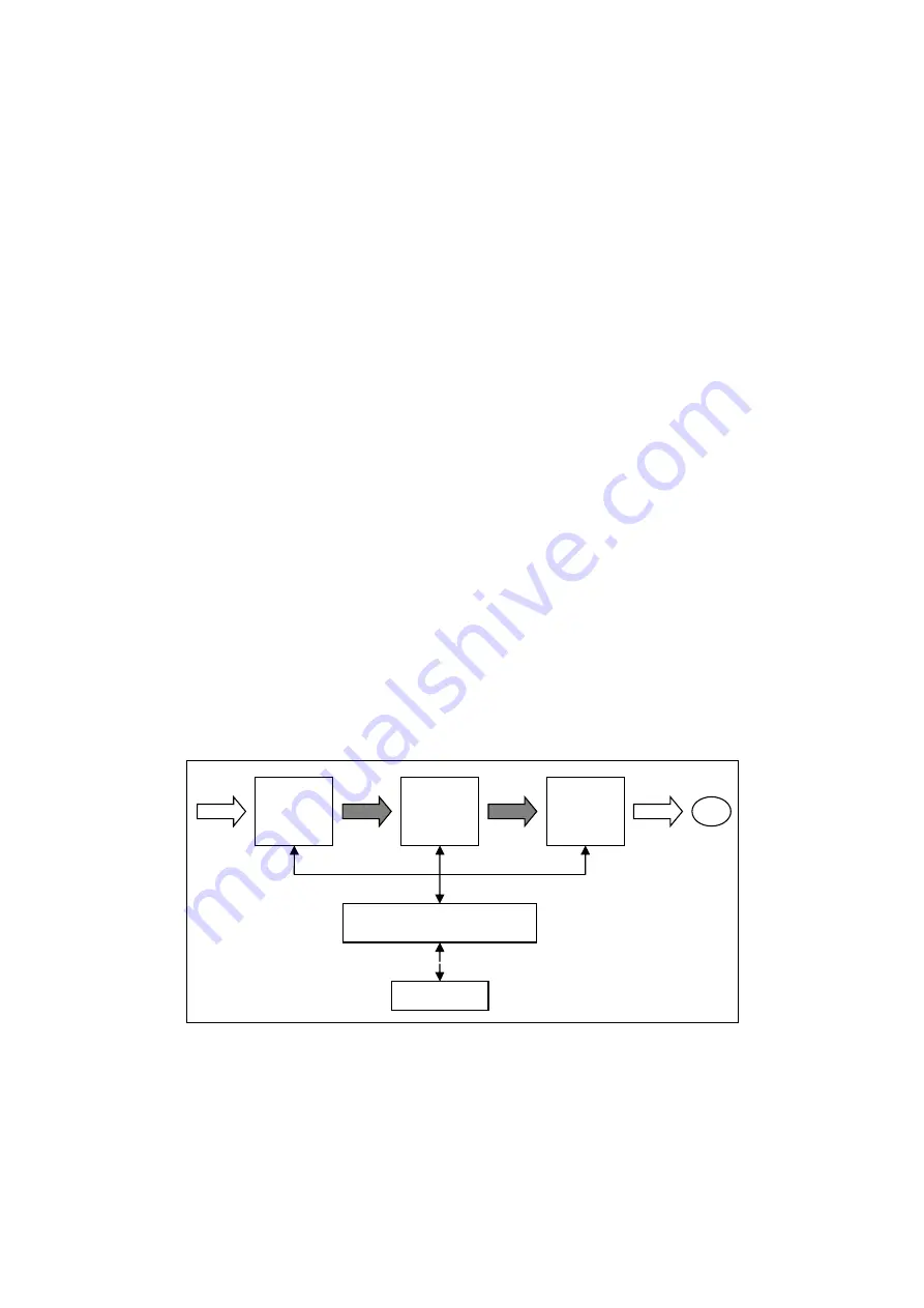
2.1 STRUCTURE OF A FREQUENCY CONVERTER
Figure 1: structure of a frequency converter
d.c.
Direct current
Rec
Rectifier
Int
IGBT intermediate driver circuit
Inv
IGBT bridge three-phase inverter
M
Motor
Cont
Control logic by micro-processor
Transm Transmission line to ext.
RAD
INT
INV
M
CONT
TRASM
1 x 230V/
3 x 400V
3 x 400V
o
3 x 230V
c.c.
c.c.


