


94MS20 Rev. B4
6-3
the autoformer is definitely bad, if the voltage on 12 and 14 in step 6 is
bad you can not get a correct reading for step 7.
8) Check capacitors and relay circuit by:
The capacitors and relays are checked by watching the voltage changes
that take place at the different intensity levels. If a capacitor is not in the
circuit the voltage readings on input and output will be the same. If the
capacitor is pulled into the circuit the input and output voltages will be
hundreds of volts apart. Now the tricky part, if a capacitor is pulled into
the circuit the way it is supposed to be then we need to look at the voltage
itself to see if we see an increase in the overall voltage to make sure that
the capacitor is adding voltage to the circuit. If the capacitor is pulled
into the circuit when it is supposed to be but the overall voltage does not
increase then the capacitor is defective.
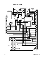
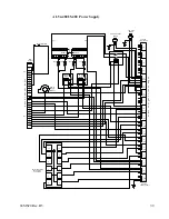
9) Check voltage from terminal 3 to the capacitor input (orange wire on top
of the capacitors). The voltage should be 500+ V~. If voltage is lower,
check the power path to the tap switch and ballasts. 500+V~ is typical
for AL 19 through AL53 light sources, 450+ V~ for 1.5 kW light sources
and 700+ V~ for the 8kW light sources. If the voltage on a 208/240V~ is
low then not all the ballasts are being powered properly. This is usually
caused by a bad tap switch or a burnt connector at the tap switch, however
any of the wiring between ballast and tap switch is suspect. If the voltage
is zero then a burnt wire at the power relay or a bad power relay is most
likely the problem. There is a possibility that if there is zero V~ that you
might have a grounded safety interlock circuit.
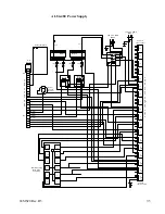
•
At idle, check voltage from terminal 3 to the capacitor outputs (yellow,
brown, and blue wires on top of the capacitors).
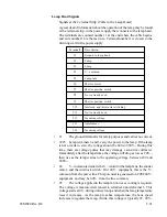
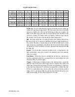
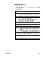
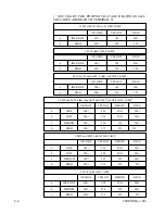
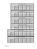
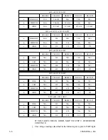
On the chart following step 6.8.5 find the Wattage of the unit you are
working on and then for the lamp installed into the unit, these are the
general voltages you should read. These voltages are a ball park figure
depending upon several factors and the actual voltage is not as important
as to whether or not the voltages change on the capacitors according to
intensity level. For instance on a 5kW light with an L1250 lamp at low
intensity one capacitor will be about 200V~ and three capacitors will be
over 500V~. Now when you go to medium intensity you should see two
capacitors at about 230V~ and two capacitors at over 500V~. NOTE the
number of capacitors at the lower voltage (i.e. in the circuit) and the
voltage increase from the previous intensity 200V~ at low and 230V~ at
medium.
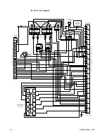
•
At low power, manual expose on, check voltage from terminal 3 to the
capacitor outputs (yellow, brown, and blue wires on top of the capacitors).
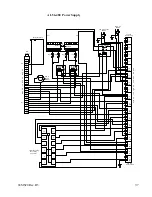
•
At medium power, manual expose on, check voltage from terminal 3 to
the capacitor outputs (yellow, brown, and blue wires on top of the
capacitors).
•
At high power, manual expose on, check voltage from terminal 3 to the
capacitor outputs (yellow, brown, and blue wires on top of the capacitors).
Summary of Contents for OLITE
Page 1: ...94MS20 Rev B4 OLITE OLITE 60Hz Printing Light Service Manual O...
Page 8: ...1 2 94MS20 Rev B4...
Page 20: ...3 10 94MS20 Rev B4...
Page 56: ...5 30 94MS20 Rev B4...
Page 86: ...7 22 94MS20 Rev B5...
Page 108: ...9 20 94MS20 Rev B4...


