


5-4
94MS20 Rev. B4
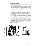
Capacitors and Level Switching
The capacitors pass all the current that flows through the lamp. They are
also used to switch power levels.
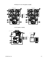
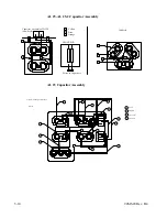
The capacitors for the light sources are divided into two or three sections.
All units have one or two idle capacitors, they are connected with a yellow
wire. There are one or two medium power capacitors (in tri-level light
sources only) connected with a brown wire. There are one or more high
power capacitors connected with a blue wire. All capacitors have an
orange wire which acts as a common.
The capacitors for high and medium levels are pulled in with relays during
warm-up and exposures. The medium relay will pull in to select medium
power. In all lights the medium relay will also always pull in for high
power exposures.
The capacitors set the operating current of the lamp. If the lamp output
has changed rapidly, inspect the capacitors for swelling. The design of
capacitor we use will burn open if it begins to short. A swollen capacitor
should be replaced, and the unit should be tested to see that the capacitor
did not damage the high or medium relay. To test the unit’s ability to
switch power levels, make a manual exposure, then switch between the
power levels, noting the change in intensity. When switching down in
power, allow the unit three seconds to respond.
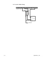
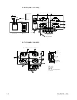
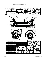
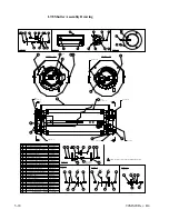
AL 83 Capacitor Assembly
Capacitor Assembly 62D127-83
D3309A
BLUE
5
4
5
BLACK
5
3
2
4
1
3 2 1
SW
Wires to Capacitors
FRONT PCB
CAPACITOR SWITCH
Black
Blue
REAR
PCB
64MV422-83
1
2
3
4
Blue / White
1
A
B
C
WIRE COLORS
2
3
4
Blue
Brown
Yellow
5
Orange
16 µƒ
10 µƒ
16 µƒ
12 µƒ
8 µƒ
Summary of Contents for OLITE
Page 1: ...94MS20 Rev B4 OLITE OLITE 60Hz Printing Light Service Manual O...
Page 8: ...1 2 94MS20 Rev B4...
Page 20: ...3 10 94MS20 Rev B4...
Page 56: ...5 30 94MS20 Rev B4...
Page 86: ...7 22 94MS20 Rev B5...
Page 108: ...9 20 94MS20 Rev B4...


