


Page 10
www.oldschoolmodels.com
Construction Manual
Step 61 - Center Section Assembly (electric power - E3)
Locate E3 from LP3.
Position your motor’s
mounting plate so
it’s centered on E3.
Typically, these plates
are in an “X” pattern, so
line it up as shown, then
drill the four mounting
holes and attach the
t-nuts to the back of E3.
Step 62 - Center Section Assembly (electric power - box)
Locate both E1s and both E2s
from LP1. These 4 pieces, along
with EP3 make the electric
motor box as shown here.
There are small relief cutouts in
the tops of E1 and E2 to allow
the blind nuts on the back of
E3 to clear. Depending on your
hardware, you may have to
adjust these gaps to fit.
When satisfied with the fit,
use epoxy to glue the pieces
together making the finished
motor box.
Step 63 - Center Section Assembly (electric power - box)
When the glue has cured, lightly sand the sides of the box smooth
to make sure it will snugly slide into the square cutout on the
electric firewall. (This firewall was installed on the center section
back on step 43.)
Do not sand too much as this should be snug fit, not a loose fit.
Step 64 - Center Section Assembly (electric power - box)
Attach the mounting plate to the motor, then the motor to the
box. it is now time to attach the box to the firewall. 30 minute
epoxy is recommended for this step, but please dry-fit everything
in position first before using glue.
A. - Slide the motor/box assembly into the cowl so the prop shaft
protrudes out the front.
B. - Attach the SP assembly to the prop shaft, making sure it is up
against the drive washer and the SP2 ring is facing the cowl.
C. - Now push this assembly on to the center section, with the
motor box sliding into the firewall until the 4 mounting tabs of the
cowl are properly located. Attach the cowl to the center section.
D. - Make sure the SP assembly is perfectly centered around the
front face of the cowl.
E. - With everything in position, you should be able to tack-glue
the motor box to the firewall in a few spots.
F. - Wait until the glue cures, then remove the SP assembly and the
cowl. You should now be left with a perfectly placed motor box
that can now be permanently glued into position using epoxy.
Step 65 - Center Section Assembly (wire/tubing)
With the powerplant in place, now you can take the time to
complete the engine installation.
• For electric, run the motor’s wires through a couple of the air
cooling openings in the motor box all the way through into the
battery compartment.
• For glow, drill holes as necessary to run the fuel lines and throttle
pushrod through the firewall.
Step 66 - Center Section Assembly (top sheeting)
Now you can finally measure, cut and glue on the remaining 1/16th
sheeting on top of the fuselage, next to the firewall.
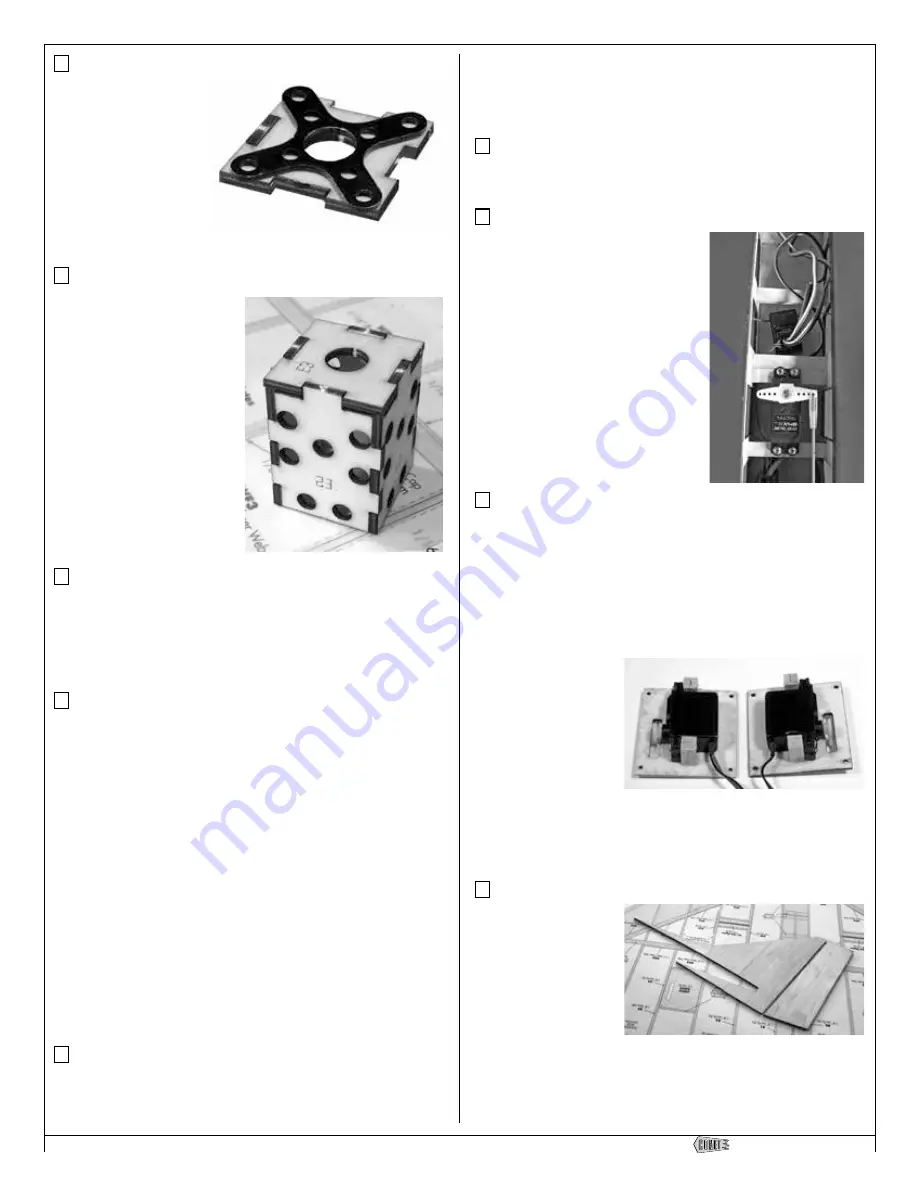
Step 67 - Servo installation (steering and rudder)
Locate 1 or 2 of your servos and mount
them to the previously installed rails in
the center section of the airframe. One
will be used if electric for the rudder
and nose steering. Two will be used if
glow as you’ll need the second one for
the throttle.
Every radio setup will be different. In
the electric prototype shown here, we
mounted the rudder servo in center of
the rails.
Step 68 - Servo installation (elevons)
From leftover 3/16” x 3/8” x 36” basswood strip, cut eight 3/4”
pieces. Make a mounting post by laminating two pieces, gluing
the 3/8” sides together to make a 3/8 x 3/8” square post. Make
3 similar posts from the remaining pieces, sanding the ends flat.
Position the aileron servo on the bottom of the aileron servo cover
so the servo arm output shaft is centered in the opening.
On the bottom of each aileron hatch, glue one post on each side
of the servo as shown in the photo.
Note that the left hatch
is a mirror image of the
right hatch.
Now fit the servo
hatches into position
on the bottom of the
wing. Using the pre-cut
holes as a guide, drill four 1/16” mounting holes into the 3/16” x
3/8”basswood mounting strips installed earlier. Harden the wood
with a bit of thin CA and you can use the attach the supplied 2-56
x 3/4” self tapping screws to secure them in place.
Step 69 - Vertical Fin (assembly)
Locate VF1, VF2, VF3
and VF4 from BP4.
These 1/4” thick parts
will make up the vertical
fin. Lightly sand the
edges to make sure they
all mate up properly,
then glue together to
make the complete vertical fin as shown here.
The piece shown separated from the fin is the rudder (VF5). We
have flown the Comet with and without rudder and you can choose


