background image

5-17 

5.14. 

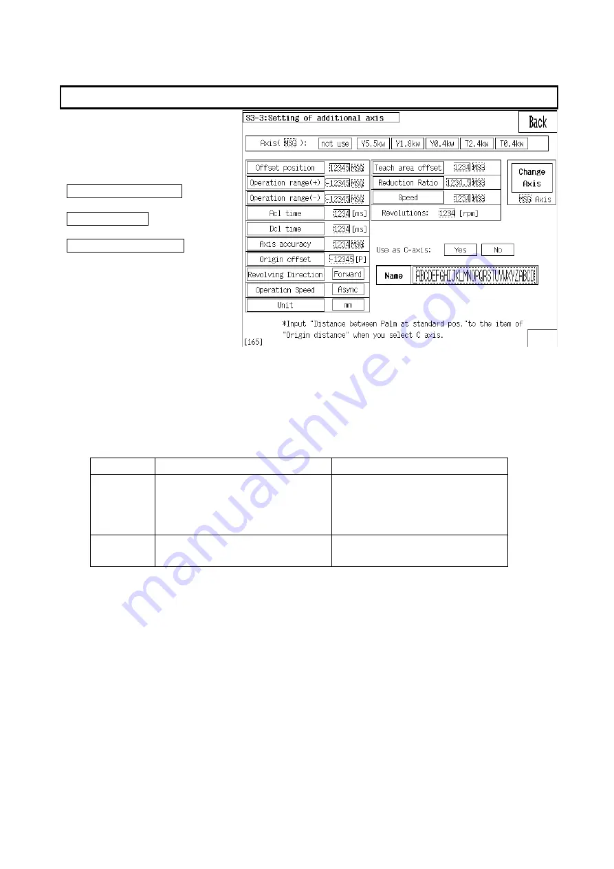
Expansion Axis Setting 

 
This screen is for setting   

expansion axis. 
The directory to expansion axis 

setting is as follows. 
 

System storage menu 


Motor axis data 


Expansion axis setting 


Note) Amp unit is required to add expansion axis. 
 

1.

Set expansion axis 

Select type of servo motor to be installed. 
 

2.

Relationship between expansion axis and C axis 

What is difference from expansion axis to be used as C axis from not as C axis. 


For C axis 

Not for C axis 

Control 

method 

Robot sequence commands 

HMOV/HMOVD/TRQC


*Can be synchronized with 

robot sequence. 

Built-in PLC commands 

EXMOVA/EXMOVR


Step 
storing 

Store per every program 
Max 9 steps per a program 

Stored per every axis 
Max 99 steps per a axis 


3.

Coordinates offset 

For the expansion axis that [Not use as C axis] is selected, enter the distance of offset 
off the position where encoder origin is stored. Normally don’t need to enter as those 

are the exact same position. 

For the expansion axis that [Use as C axis] is selected, enter the distance between 

palms (paddles) where encoder origin is stored. Normally don’t need to enter as those 
are the exact same position. 


4.

Operation range+- 

Enter operation range for the expanded area. 


5.

Acceleration / deceleration time 

Enter Acceleration / deceleration time. 


6.

Axis accuracy 

Summary of Contents for A Series

Page 1: ...Okura Yusoki Co Ltd Robot Manual Installation and Adjustment Electrical UL CE VINSE 01 Original instructions...

Page 2: ...History Version Date Content Page 01 2012 04 24 First edition...

Page 3: ...ach A Series Robotic Palletizer is equipped with a variety of protective features However an increased level of safety results when these safety precautions are constantly reviewed and consistently fo...

Page 4: ......

Page 5: ...CTOR UNIT MCRU 1 UL CE 3 7 3 5 SAFETY RELAY BOARD RC516 3 8 3 6 AMP UNIT 3 10 3 7 FIELDBUS BOARD ETHERNET IP AB6214 3 11 4 ADJUSTMENTS 4 1 4 1 ORIGIN STORING 4 2 4 2 BASIC POSTURE 4 4 4 3 AMP UNIT 4 5...

Page 6: ...Y REPLACE 6 12 6 10 CONVEYOR INFORMATION 6 12 6 11 STACKED COUNTER REVISION 6 13 6 12 PROGRAM SELECTION METHOD 6 14 6 13 POSITION ACCELERATION DECELERATION TIME 6 14 6 14 EXECUTED SEQUENCE COMMAND 6 1...

Page 7: ...1 1 1 Outline of Controller Names of part of controller and main parts are introduced in this section...

Page 8: ...1 2 1 1 Appearance of Controller 1 1 1 Robot Controller This is common among RC830 and RC840 See 5 SYSTEM SPECIFICATIONS for model of controller for detail...

Page 9: ...nel Only Teaching pendant works at manual mode Note Manual operation on controller does not work once teaching pendnat is connected How to set up teaching pendant See Operation Manual Section 4 E S pu...

Page 10: ......

Page 11: ...2 1 2 Harness Cable Connection...

Page 12: ...O motor CN16 CN11 R motor CN12 CN8 CN9 CN10 CN7 CN2 CN3 RM815 RM816 RM817 RK831 RM832 RK833 CN6 CN18 CN4 CN22 D encoder CN23 O encoder CN24 CN26 CN31 RM851 RM852 RK853 RK854 RK855 RK873 RM856 CN34 RK...

Page 13: ...CN24 CN26 CN31 RM751 RM752 RK753 RK754 RK755 RK773 RM757 CN34 RK758 CN21 R encoder T AXIS HAND CN37 CN5 BAT CN17 T motor CN25 T encoder CN33 CN32 RK774 CN36 CN35 RM771 RK781 RK782 AIR 12mm 10mm 12mm...

Page 14: ...RK762 RK763 RM764 RK765 RK773 RK767 CN34 RK768 CN21 R encoder ROTOR HAND CN37 CN5 BAT CN17 T motor CN25 T encoder CN33 CN32 RK774 CN36 CN35 RM770 RK781 RK782 AIR 12mm 10mm 12mm 12mm AIR 12mm R LS RK7...

Page 15: ...nector in controller Connector No Pin No Wire No Connector No Pin No Wire No Wire size 3 S3 1 S3 4 S4 2 S4 13 S5 3 S5 CN33 3191 15R1 14 CLS CNH2 F31FSS 05V KX 4 CLS 1 S6 A1 S6 2 S7 A 2 S7 3 S8 A 3 S8...

Page 16: ...ive conductors vend wire adequately if needed And fix them firmly so that not to strain on the terminal Specification of main power supply wires Wires UL standard Wires size minimum AWG 10 Conductor c...

Page 17: ...ween robot body and protective conductors inside controller Wires IEC standard Wires diameter more than 10 sqmm Color green yellow 2 Measure resistance value between each motor frames and external pro...

Page 18: ...onveyors need to be installed following the below way 1 The cables to enter through opening at bottom of panel need to be fixed around opening to not come out The cables are fixed by saddles to bracke...

Page 19: ...rvo Power Unit RC516 Safety Board RC501 Board AP507 AP504 Amp Unit Servo motor Servo motor Servo motor Servo motor axis D axis O axis T axis Touch Panel POD OXPA Teaching Pendant AP507 AP504 Amp Unit...

Page 20: ...CPU board is as follows DIP switch DSW1 Explanation No Descriptions Default setting Firmware Serial transfer OFF System reserve OFF System reserve OFF System reserve OFF Motor rotation test OFF Syste...

Page 21: ...access D Master DSP 7 segment display D 7seg Slave DSP D O axis 7 seg display D 7seg Slave DSP R T axis 7 seg display D 7seg Slave DSP C X axis 7 seg display D Memory backup battery voltage dropped D...

Page 22: ...5 3 4 Close Master DSP watchdog setting 2 3 Close ADC reference power setting on slave DSP 1 2 Close Connection with analog and digital GND Open Connection setting with FG SG CN6 Close Not installed y...

Page 23: ...the I O board is as follows Jumper Pin Explanation Signs Descriptions Default setting JP1 JP2 JP3 Board address setting 1st Only JP1 close 2nd Only JP2 close 3rd Only JP3 close LED Explanation LED No...

Page 24: ...ows Jumper Pin Explanation Signs Descriptions Default setting JP1 Switching supply voltage over close LED Explanation LED No Lighting condition LD1 Regen resistor temperature failure LD2 Soft charging...

Page 25: ...3 7 3 4 Contactor Unit MCRU 1 UL CE Neither LED nor jumper pin is on contactor unit...

Page 26: ...A I O Type selection 1 Upto system JP B I O Type selection 1 Upto system RC516B board is supposed to be shipped out being set on Source default Don t use any IC else instead of the attached to replace...

Page 27: ...se line LED6 Brake release line LED7 Operation mode switch manual line 1 LED8 Operation mode switch manual line 2 LED9 Motor power switch neutral position LED10 Motor power switch turning on LED11 Rea...

Page 28: ...Board IPM type Board IPM type R axis RC507 PM200CL1A060 RC504 PM100CL1A060 D axis RC507 PM200CL1A060 RC504 PM100CL1A060 O axis RC507 PM200CL1A060 RC504 PM100CL1A060 T axis C axis RC508 PS21765 RC508 P...

Page 29: ...nections established Red Duplicate IP address FATAL error Red flashing One or more connections timed out CIP Class 1 or 3 Module Status LED Note A test sequence is performed on this LED during startup...

Page 30: ......

Page 31: ...4 1 4 Adjustments...

Page 32: ...re the origin However when motors etc are replaced do Temporal storing just to move arm near the origin first in PTP mode then do the origin storing second CP PM mode doesn t work for manual operation...

Page 33: ...2 Bit 1 O axis 4 Bit 2 R axis 8 Bit 3 T axis When the errors in the two or more axes are generated Sub No becomes a total of the number Danger Enforcement The origin storing must be appropriately cond...

Page 34: ...igin With A1600V A700VSeries Move the R axis and align the scribed lines on the base and base With A1800V Move the R axis and align the match marks on the base and rotor D 0 degree horizontal is taken...

Page 35: ...n power down Disconnect the connectors to from amp unit and wiring to terminals Unbolt the mounting screws out of amp unit Replace whole unit including bracket and heat sink at a time Connect the conn...

Page 36: ...ger the value of the servo parameter set is the larger the threshold is So the detection falls down to less sensitive It becomes more difficult to properly detect On the contrary the smaller the value...

Page 37: ...g was made motor has been replaced or other maintenance has been conducted The directory to the system storage menu screen is Select S System storage mode on basic menu and enter the password to go Sy...

Page 38: ...name Enter conveyor names at the conveyor manual mode screen Pressing number of item you want allows to turn to the input mode 5 2 Communication Setting The serial communication format of S I O port i...

Page 39: ...ow when Centronix is set up Error notice If Do is selected error code is notified to PLC when error occurs inside controller Prg No addition If Do is selected upper 6 bits and lower 6 bits are added n...

Page 40: ...et value is selected it is allocated as follows Remote output RY M5000 Remote input RX M6000 Remote register RWw D5000 Remote register RWr D6000 Input data when data link is failed If Data clear is se...

Page 41: ...g Select an item to be reset by pressing a key Press Clear key Note The memory switch 1 5 is turned on to make this setting effective As the standard password is master one it still works even after t...

Page 42: ...lid if the password has been set in the system parameter screen Password is invalid All OFF 1 6 DMOV movement T axis is non synchronized Only T axis moves to the target position directly T axis is syn...

Page 43: ...dard All OFF 3 1 PC communicatio n restriction Disable to download from PC while motor power is on Normally enable to download All ON 3 2 Collision Detection Valid Invalid All OFF 3 3 System reserve A...

Page 44: ...5 8 SW No Name ON OFF Type Default 5 8 6 1 6 2 6 3 6 4 6 5 6 6 6 7 Note Pressing No of switches allows to display its explanation at bottom of screen...

Page 45: ...Enter the job number you work on The job number is shown up at the basic menu Top of latch range The range on and after the device No is set becomes latched Number of I O board Number of RC502 boards...

Page 46: ...in the list allows to be reversed into blue color External memory USB CF to be used can be selected by pressing USB CF button When USB memory is used insert a USB memory stick into controller before o...

Page 47: ...ted Don t use this normally System file backup Export Whole the files stored into RC501 are saved into folder of BACKUP in a external memory If there is already a folder of BACKUP a confirmation messa...

Page 48: ...changed Then enter a value to be set by numeral keys and press WRITING key User time clear Press TIME CLEAR key after pressing the USER TIME key All the items of the user time are cleared to 0 Mainten...

Page 49: ...n This cannot be set or changed by the user Numerical value is of the number of encoder pulse meaning a deviation between the encoder pulse origin and robot base posture origin 1 Acceleration Decelera...

Page 50: ...tia of T axis Enter the inertia of T axis Enter 0 if don t want Number of T axis revolution Enter the max number of T axis revolution Enter 0 for the default Number of steps of C axis Enter number of...

Page 51: ...d motion The bigger value the shorter linear motion 4 100 SMOV inner judgment Speed regulation for RX motion 5 100 0 100 SMOV inner judgment Speed regulation for RZ motion 6 100 Step1 effective height...

Page 52: ...he servo control The directory to the servo parameter screen is as follows System storage menu Motor axis data Servo parameter IMPORTANT Each parameter should be of within a due range otherwise the ro...

Page 53: ...ed with robot sequence Built in PLC commands EXMOVA EXMOVR Step storing Store per every program Max 9 steps per a program Stored per every axis Max 99 steps per a axis Coordinates offset For the expan...

Page 54: ...change by itself the speed proportional to robot auto operation speed To select Asynchronize allows to operate it according to the specified Unit Select mm or deg angle Teaching range offset margin Th...

Page 55: ...6 1 6 Maintenance Functions Maintenance on Touch panel POD is explained...

Page 56: ...To move to maintenance menu under operation press the hidden key located below on the auto mode screen In the case of returning from maintenance menu it returns to auto mode screen instead of back to...

Page 57: ...6 1 2 Maintenance menu detail The maintenance menu branches off to Controller data Robot data and Motor axis data Versions of software are displayed over here Controller data Motor axis data Robot da...

Page 58: ...ion for the 1st bag D 13 stop position for the 2nd bag D 14 centering position D 15 pressing height D 4 11 universal External data memory D 1000 D3999 user area D 5000 D 5999 system and user area the...

Page 59: ...r a program are available Those are used for relay logical operation Universal usage Force procedure Press a relay displayed that you want to change External relays The allocation of external relay No...

Page 60: ...on In case either motor power or operation is not turned check if every condition in this screen comes on 2 You can see the status of inputs outputs ON OFF to from each CPU at bottom of screen 6 5 Ke...

Page 61: ...case Pressing No in the list allows to select file to be transferred or deleted The selected file turns to reversed blue color External memory can be selected with USB or CF Folder of external memory...

Page 62: ...prepared by computer Folder structure of external memory Work folder Create a folder on root directory in external memory with a exact same name as job number set at S1 6 Parameter setting screen see...

Page 63: ...setting After entering relay No press No at left side to be highlighted in red color The highlighted is trigger Trigger level setting Touching TRIGER EDGE at bottom left allows to toggle between UP or...

Page 64: ...tton is changed whenever pressed Impossible to set up under RUN status Even if screen is switched over the status of RUN STOP can be kept Once triggered it comes to STOP status How to see data after t...

Page 65: ...tion can be shown and registered To press Cancel allows to cancel all the allocation of IDNo 1 to 127 To press Change allows to display IDNo allocation change screen ID No assignment change 1 Enter ID...

Page 66: ...d Note If wrong date is entered waring message for replacing battery will be wrong accordingly 6 10 Conveyor information The directory to conveyor information is as Follows Maintenance menu Controller...

Page 67: ...ction the counter values of all pallet 1 6 are initialized Press Initialize All Programs key to initialize the counter values of all program stored in robot counter Counter Revision Counter value of e...

Page 68: ...cedure on manual of Teaching pallet on floor for detail 6 13 Position acceleration deceleration time The directory to acceleration Deceleration time screen is as follows Maintenance menu Robot data Po...

Page 69: ...downward to show you all the rest of the commands Screen explanation 1 Executed sequence No Numbering is made in order of new to old 2 Program No Program Nos to be executed are displayed 3 Line No Li...

Page 70: ...step No position data and acc dec time are displayed when SMOV is executed 6 17 Deviation trace The directory to deviation trace is as follows Maintenance menu Motor axis data Deviation trace It displ...

Page 71: ...shown But in case a motor power is off the data is not updated by itself In case a motor power is turned off by occurrence of failure the data for about 20 seconds before the error can be shown Press...

Page 72: ...ured it is cancelled Press Save To File to save the measured data The data saved to file can be taken in by OXPA Qm as CSV file Press Data display key to show speed torque in graph Selecting axis allo...

Page 73: ...lows Maintenance menu Motor axis data Collision detection trace 6 21 Expansion axis trace The directory to expansion axis trace is as follows Maintenance menu Motor axis data Expansion axis trace It s...

Page 74: ......

Page 75: ...y computer Number of simultaneous loading points Max 14 pallets 4 stations Repeat speed 10 levels 1 10 Editor functions Revise Addition Delete Transfer Copy Labels Outside Teaching Operation Remote op...

Page 76: ......

Page 77: ......

Page 78: ...01 2012 04 24 Caution Unauthorized reproduction of part or all of the content of this manual is forbidden The content of this manual is subject to future change without prior notice Okura Yusoki Co L...

Reviews: