background image

Install/Uninstall USB drivers on Windows

17

2.1.2 Uninstall USB drivers on Windows XP

If you need to delete the USB drivers from your operating system because of a wrong installation, please 

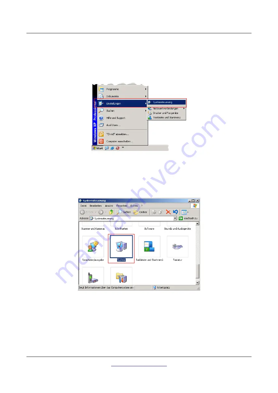
open   the   device   manager   of   Windows   XP.   Therefore   please   click   on   Start   >   control   panel,   like 
represented in figure 2.7.

After that a dialog like in figure 2.8 appears. There you can find the entry system and click twice on it.

The dialog from figure 2.9 appears on your screen. Click on the tab hardware and after that the button 
device manager.

OKM Ortungstechnik GmbH

www.okmmetaldetectors.com

Illustration 2.7: Uninstall USB drivers: Windows 

XP, Step 1

Illustration 2.8: Uninstall USB drivers: Windows XP, Step 2

Summary of Contents for eXp 4000

Page 1: ...FS Future Series eXp 4000 Version 2 1 User s Manual ...

Page 2: ...n no circumstances OKM takes responsibility for lost profits usage or data losts interruption of business activities or all kind of other indirectly damages which developed because of errors in this documentation This instruction manual and all other stored media which are delivered with this package should only be used for this product Program copies are allowed only for security and savety purpo...

Page 3: ...ers on Windows Vista 20 2 2 2 Update USB drivers on Windows Vista 22 2 2 3 Uninstall USB drivers on Windows Vista 26 2 3 Windows 7 27 2 3 1 Install USB drivers on Windows 7 27 2 3 2 Uninstall USB drivers on Windows 7 32 3 Technical Specifications 33 3 1 Control Unit 34 3 2 Data Transmission 34 3 3 Computer Minimum Requirements 34 4 Scope of Delivery 35 5 Assembly 37 6 Control Elements 41 6 1 Contr...

Page 4: ... advices for field procedure 61 8 2 1 Orientation of probe 62 8 2 2 Parallel or Zig Zag 62 8 2 3 Manual or automatic impulse mode 63 8 2 4 Tips from the trainers themselves 63 9 Optional Equipment 65 9 1 Super Sensor 66 9 1 1 Usage 66 9 2 DDV system 67 9 2 1 Calibration 67 9 2 2 Adjust the discriminator 69 9 2 3 Ground Balance 70 10 Error Messages 71 OKM Ortungstechnik GmbH www okmmetaldetectors c...

Page 5: ... Vista Step 5 24 Illustration 2 22 Update USB drivers on Windows Vista Step 6 24 Illustration 2 23 Update USB drivers on Windows Vista Step 7 25 Illustration 2 24 Uninstall USB drivers on Windows Vista Step 1 26 Illustration 2 25 Uninstall USB drivers on Windows Vista Step 2 26 Illustration 2 26 Install USB drivers on Windows 7 Step 1 27 Illustration 2 27 Install USB drivers on Windows 7 Step 2 27...

Page 6: ...llustration 7 14 Signature of a non metallic target 53 Illustration 7 15 Empty Memory 54 Illustration 7 16 Exit 54 Illustration 9 1 Position of Super Sensor 66 Illustration 9 2 Control Elements of the Detector 67 Illustration 9 3 Calibration of the DDV system step 1 68 Illustration 9 4 Calibration of the DDV system step 2 68 Illustration 9 5 Adjustment of discrimination 69 Illustration 10 1 Only a...

Page 7: ...1 Introduction CHAPTER 1 Introduction ...

Page 8: ...earch that you will be successful and have a find The recognition of hidden and buried objects depends on a huge number of factors As you well may know there are different soil types all over the world with different levels of natural attenuation Variable soil properties can and will hamper and alter ultimate scan measurements Areas where there is an extreme amount of ground water varying clays sa...

Page 9: ...le parts on the inside of the unit 1 2 2 Possible Health Hazards If used properly this device normally does not pose any health hazards According to current scientific knowledge the high frequency signals are not harmful to the human body on account of their low power 1 2 3 Surrounding Area When moving this unit from a cold place to a warmer place watch out for condensation Do not immediately oper...

Page 10: ...and accumulators are fully charged Also allow the batteries to completely discharge before recharging them regardless if you are working with the external battery or with internal accumulators This way your batteries will have a long and durable life To charge the external and internal batteries use only the approved chargers which are part of our scope of delivery 1 4 Danger of Explosion during E...

Page 11: ...ave been rusting away in the course of time and the slightest movement may cause parts of them to break and be triggered Even seemingly harmless objects such as cartridges or large ammunition are anything but that Explosives may have become crystalline over time that is sugar like crystals have formed Moving such an object may cause those crystals to produce friction leading to an explosion If you...

Page 12: ......

Page 13: ...Uninstall USB drivers on Windows In this chapter you will learn how to install the USB drivers that are necessary to transfer data from the machine to your computer software Please make sure to read the proper section appropriate to your Windows operating system ...

Page 14: ...pears on your screen If your Windows XP has Service Pack 2 installed you will see the dialog from figure 2 2 if Windows Update has to search for drivers up to date Mark entry No not this time and click on Next In other versions of Windows this window should not appear In the following dialog window like figure 2 3 select the entry Install software from a list and click Next OKM Ortungstechnik GmbH...

Page 15: ...efore click on Data carrier Immediately another window appears where you click on the button Search Then select the file OKM_LE INF which you can find in the directory drivers usb_cable of your software CD Afterwards you have to click on Open OK and Next to start the installation of the files OKM Ortungstechnik GmbH www okmmetaldetectors com Illustration 2 3 Install USB drivers Windows XP Step 3 I...

Page 16: ...e like in figure 2 6 will appear on your computer screen Now the drivers of your device are installed and you can transfer data to your PC OKM Ortungstechnik GmbH www okmmetaldetectors com Illustration 2 5 Install USB drivers Windows XP Step 5 Illustration 2 6 Install USB drivers Windows XP Step 6 ...

Page 17: ... click on Start control panel like represented in figure 2 7 After that a dialog like in figure 2 8 appears There you can find the entry system and click twice on it The dialog from figure 2 9 appears on your screen Click on the tab hardware and after that the button device manager OKM Ortungstechnik GmbH www okmmetaldetectors com Illustration 2 7 Uninstall USB drivers Windows XP Step 1 Illustrati...

Page 18: ...le USB devices will be shown Mark the device which you like to delete which means eXp 4000 Additionally the device may be listed as OKM Quick Link Then click on the button Alternatively you can select the entry Uninstall in the menu Action OKM Ortungstechnik GmbH www okmmetaldetectors com Illustration 2 9 Uninstall USB drivers Windows XP Step 3 Illustration 2 10 Uninstall USB drivers Windows XP St...

Page 19: ...ure 2 11 appears Click there on the button OK Now all drivers will be deleted from your computer If needed you can now install the USB driver again correctly OKM Ortungstechnik GmbH www okmmetaldetectors com Illustration 2 11 Uninstall USB drivers Windows XP Step 5 ...

Page 20: ...ista is relatively simple After you have connected the device with your computer switch it on and the message from figure 2 12 appears on your screen Click on Locate and install driver software recommended At the next window shown in figure 2 13 click on Don t search online OKM Ortungstechnik GmbH www okmmetaldetectors com Illustration 2 12 Install USB drivers Windows Vista Step 1 Illustration 2 1...

Page 21: ... has finished the completion screen from figure 2 15 is displayed Press Close to close this window Now you have completed the installation of the USB drivers in Windows Vista which will be confirmed by presenting the message from figure 2 16 OKM Ortungstechnik GmbH www okmmetaldetectors com Illustration 2 14 Install USB drivers Windows Vista Step 3 Illustration 2 15 Install USB drivers Windows Vis...

Page 22: ...the Device Manager of Windows Vista Therefore press the Windows start button and click on Control Panel At the next screen shown in figure 2 18 select View hardware and devices which can be found on the bottom of the left sidebar OKM Ortungstechnik GmbH www okmmetaldetectors com Illustration 2 17 Update USB drivers on Windows Vista Step 1 Illustration 2 18 Update USB drivers on Windows Vista Step ...

Page 23: ...this device will depend on the device attached In this example the device was an eXp 4000 device Right click on the device eXp 4000 in this example to bring up a menu as shown below From the displayed menu select Update Driver Software which then displays the option for an automatic or manual search Select the second option to browse manually OKM Ortungstechnik GmbH www okmmetaldetectors com Illus...

Page 24: ...ct same location as shown in the screenshot of figure 2 28 After entering the drivers location select Next to start the installation When the installation has finished the completion screen from figure 2 17 is displayed Press Close to close this window and go back to the Device Manager OKM Ortungstechnik GmbH www okmmetaldetectors com Illustration 2 21 Update USB drivers on Windows Vista Step 5 Il...

Page 25: ... Universal Serial Bus Controllers indicated in the screenshot below as OKM Quick Link The USB drivers are correctly updated installed now and you can close the Device Manager window OKM Ortungstechnik GmbH www okmmetaldetectors com Illustration 2 23 Update USB drivers on Windows Vista Step 7 ...

Page 26: ...g on the mouse and selecting Uninstall This will delete the associated registry entries for that device only Windows Vista provides an automatic method to delete driver files via check box Delete the driver software for this device on the uninstall dialog box Just mark the check box and click OK to remove the installed USB drivers of your device OKM Ortungstechnik GmbH www okmmetaldetectors com Il...

Page 27: ...s now trying to install the latest USB drivers and displays the message from figure 2 19 Shortly after this Windows 7 will bring up a new message as shown in figure 2 20 to inform you about the fact that it could not install any drivers for your device successfully Press the Windows 7 start button to bring up the start menu and select Control Panel as shown in figure 2 26 OKM Ortungstechnik GmbH w...

Page 28: ...ol panel window you have to select Hardware and Sound At the next screen shown in figure 2 30 select Device Manager which can be found under Devices and Printers OKM Ortungstechnik GmbH www okmmetaldetectors com Illustration 2 29 Install USB drivers on Windows 7 Step 4 Illustration 2 30 Install USB drivers on Windows 7 Step 5 ...

Page 29: ... this example the device was an eXp 4000 device Right click on the other device eXp 4000 in this example to bring up a menu as shown below From the displayed menu select Update Driver Software which then displays the option for an automatic or manual search Select the second option to browse manually OKM Ortungstechnik GmbH www okmmetaldetectors com Illustration 2 31 Install USB drivers on Windows...

Page 30: ...exact same location as shown in the screenshot of figure 2 31 After entering the drivers location select Next to start the installation When the installation has finished the completion screen from figure 2 32 is displayed Press Close to close this window and go back to the Device Manager OKM Ortungstechnik GmbH www okmmetaldetectors com Illustration 2 33 Install USB drivers on Windows 7 Step 8 Il...

Page 31: ...under Universal Serial Bus Controllers indicated in the screenshot below as OKM Quick Link The USB drivers are correctly installed now and you can close the Device Manager window OKM Ortungstechnik GmbH www okmmetaldetectors com Illustration 2 35 Install USB drivers on Windows 7 Step 10 ...

Page 32: ...ing on the mouse and selecting Uninstall This will delete the associated registry entries for that device only Windows 7 provides an automatic method to delete driver files via check box Delete the driver software for this device on the uninstall dialog box Just mark the check box and click OK to remove the installed USB drivers of your device OKM Ortungstechnik GmbH www okmmetaldetectors com Illu...

Page 33: ...3 Technical Specifications CHAPTER 3 Technical Specifications ...

Page 34: ...Data Memory 256 MB Feedback accustic visual Storage temperature 20 C 60 C Air humidity 5 75 Waterproof No Sensor technology TCFX 01 A 3 2 Data Transmission Technology USB Maximal Data Transmission Rate 19200 Baud 3 3 Computer Minimum Requirements The computer is not part of the scope of delivery The indicated values should help you for a correct selection of a suitable computer for analysis of you...

Page 35: ...4 Scope of Delivery CHAPTER 4 Scope of Delivery ...

Page 36: ...ap 1 1 1 Headphones 1 1 1 Telescopic rod assembly for GPR antenna 1 1 1 Power Pack with charger and travel adapter 1 2 1 GPR antenna 25 cm 1 1 1 Joystick 1 1 1 User s manual 1 1 1 Carrying case 1 1 2 3D Software Visualizer 3D 1 1 1 USB cable 1 1 1 Super sensor 1 1 Antenna for metal discrimination DDV system 1 1 GPR antenna 50 cm 1 GPR antenna 75 cm 1 GPR antenna 100 cm 1 Antenna for tunnel detecti...

Page 37: ...5 Assembly CHAPTER 5 Assembly This section explains how to assemble the eXp 4000 and to prepare the unit for operation ...

Page 38: ...e using you will always use the same plug for each probe You can only use one probe at a time for one measurement Illustration 5 2 Connection of Power Pack Step 2 Now you can connect the Power Pack to the control unit After powering on the Power Pack you can put it in your pocket Now you should power on the device by using the Power On Off button Illustration 5 3 Connection of headphones Step 3 Th...

Page 39: ...sembly 39 OKM Ortungstechnik GmbH www okmmetaldetectors com Illustration 5 4 Connection of joystick Step 4 If you are going to be conducting a scan in Manual mode plug in the joystick to the control unit ...

Page 40: ......

Page 41: ...ments CHAPTER 6 Control Elements In this section you will learn more about the fundamental use of all control elements for the eXp 4000 measuring instrument All connections inputs and outputs are explained in detail ...

Page 42: ...onnected via the T mount to the Telescopic rod assembly Vertical probes like the Super Sensor can simply be held in your hand OKM Ortungstechnik GmbH www okmmetaldetectors com Illustration 6 1 Control unit with power supply and probe Headphones Control unit External power supply Supersensor T mount GPR probe 25 cm Carrying strap Telescopic rod assembly ...

Page 43: ... external Power Pack and turn it on The Start button is used to start a scan When in Manual mode it is also a secondary trigger to record a measurement The joystick Connector is used to connect the joystick to the device The joystick fullfils the same functions as the Start button but is more comfortable and can facilitate the measurement procedure OKM Ortungstechnik GmbH www okmmetaldetectors com...

Page 44: ...e connector the different probes as well as the DDV system can be connected The connector for the headphones is used to plug in the delivered headphones enabling the user to hear an audio output Via the connector for the USB cable the device can be connected to a computer via the USB cable This is necessary to transfer data from the device to a computer OKM Ortungstechnik GmbH www okmmetaldetector...

Page 45: ...7 Operating Modes CHAPTER 7 Operating Modes In this section you will learn more about the different operating modes of the eXp 4000 Every function is explained in its proper subsection ...

Page 46: ...ts regarding their characteristics on iron contents Empty Memory Delete all data stored in the internal memory Exit Power off the device and shut down the integrated PC module If you are connecting the optional FS Thermoscan to the eXp 4000 there will be two more operating modes available Without FS Thermoscan those functions are inactive and not visible Thermograph This operating mode is used to ...

Page 47: ...g on the unit above a neutral soil all metallic signatures will be shown in upward spikes If by mistake you start the unit above a metal target all like metals will not be recognized To re balance the Magnetometer press the OK button while staying on a neutral place To exit the Magnetometer mode press the or to return to the main menu When you use this mode you can actually move quite quickly to c...

Page 48: ...disturbance in the soil first If a hole was created at 4 feet 1 5m deep after a couple of seasons the hole will appear to be over 6 ft 2m in diameter at the surface Start with a scan that has an impulse approximately every 1 to 2 feet 40cm 60cm forward and to the sides Don t go too fine on the first scans until you have a possible anomaly Look for the holes Usually without a hole you could be look...

Page 49: ...ured values will be recorded represented on the display continuously Impulses Auto 10 20 50 Number of measured values per search line If you select Auto the number of impulses can be adapted to the current length of your search line During the first line the device will read values regulary without stopping When you want to finish your first line you have to press the OK key to stop the measuring ...

Page 50: ...nt value is highlighted in red color Now you can change the value of the selected parameter by using the keys and To finish this process you have to press the OK key again Go to your start position and adjust all necessary parameters to your needs Then you have to select option Start Scanning to start the measurement The message from figure 7 6 will appear and ask you if you are ready to start you...

Page 51: ...nterferences in blue colors Areas where ground mineralization is present is often shown in red also 7 2 2 Browse Scans After selecting the Browse Scans function with the OK key you will see a list of the stored scans as represented in figure 7 8 Select the measurement which you like to see with the keys and For the selected measurement the following options represented in figure 7 9 are provided O...

Page 52: ... to go back to the selection menu Delete Scan Image The current selected measurement will be deleted if you confirm the following message with Yes Following you will go back to the menu Ground Scan Back To Ground Scan Menu You go back to menu Ground Scan OKM Ortungstechnik GmbH www okmmetaldetectors com ...

Page 53: ...e Also with this detector you have the possibility to discriminate between different metals So for example you can find out if an object is gold silver or iron Further information about the correct usage of the detector and the principle of discrimination you can find in section Optional Equipment DDV system of this users manual OKM Ortungstechnik GmbH www okmmetaldetectors com Illustration 7 10 M...

Page 54: ...ed possible objects and now want to know more details about them The Supersensor should point vertical towards the ground It should not be turned or pivoted Now you can slowly move the Supersensor from one side to another above the possible object Please try to capture the complete object which means you should measure beyond the edges of the object Repeat this measurement a few times to get a cle...

Page 55: ...The last of the typical signatures is represented in figure 7 14 It is the signature of all non metallic targets and structures These can be voids tunnels or buried plastic pipes or boxes You can recognize that there is only a negative amplitude blue 7 5 Empty Memory The Empty Memory mode is used to delete all data which is stored in the internal memory of the device If you confirm this option you...

Page 56: ...rnal power supply 7 7 Thermograph This operating mode is only visible and usable if the optional device FS Thermoscan is connected Detailed information about this functionality is available in the user s manual of FS Thermoscan 7 8 Thermo Scan This operating mode is only visible and usable if the optional device FS Thermoscan is connected Detailed information about this functionality is available ...

Page 57: ...ield procedure CHAPTER 8 Field procedure This chapter gives practical instructions about the general procedure of scanning an area The different scanning methods and procedures will be explained in detail ...

Page 58: ...oint for your measurement by yourself The scanning paths may be referred as Zig Zag or Parallel traverses Also the number of impulses measure points which are recorded during one scanning path can be adjusted individually depending on the size of your scan area length of scanning path 8 1 1 Scan Mode There are two general techniques to surveying an area with the eXp 4000 Zig Zag The starting posit...

Page 59: ... If you mostly look for smaller targets than you should also select a smaller distance between the lines A standard rule is The smaller the distance between the paths the more accurate your scans will be When you are conducting your first scans the lines should not be to close together to locate possible targets 8 1 2 Regulation of the number of impulses per scanning path It is possible to select ...

Page 60: ...l be If you are looking for small objects you have to select a smaller distance for big objects you can increase the distance between the impulses Figure 8 3 shows the effects of the distance and the number of impulses per scanning path for some objects Figure 8 4 shows the difference between very few impulses left side and much more impulses right side on the same length of scanning path Therefor...

Page 61: ...s for field procedure There are some aspects which you should take note of when conducting scans In principle a scan is only as good as the path that was taken Making errors while scanning will show up in the final graphical representation also as an error This will cause frustration and lost time Before you start with a measurement in the field you should think of what you are looking for and if ...

Page 62: ... the same distance to the ground Generally we recommend a height of about 5 15 cm from the surface of the ground if possible In the event that you are going to go over stones wood or high grass that is higher start your scan with the sensor higher right from the beginning In circumstances like these then perhaps you will need to start the scan with the probe at a height of 2 feet 50 cm and keep it...

Page 63: ...the soil and creates some kind of noise Usually the buried object has a weaker signature than the unnatural noise and therefor is not detectable So taken scan images will not show the buried item but visualize the noisy area in blue colors After the item has been seasoned meaning it has been in the ground for a complete cycle of seasons usually a year the noise gets reduced and the signature of th...

Page 64: ...here are two factors of sand that need to be noted Sand where the ground water is very shallow meaning that the ground water is usually just a couple of meters from the surface or desert sand where it is very arid In desert sand the targets can be situated 3x deeper than indicated Farmland is another area to take note of In modern farms so many nutrients and fertilizers are introduced creating an ...

Page 65: ...ment CHAPTER 9 Optional Equipment Here you can find additional information on accessories that can compliment the basic unit Keep in mind that the mentioned accessories are not included in the normal scope of delivery ...

Page 66: ...you just have to connect it to the main unit Therefore you have to plug in the connector of the antenna in the appropriate input of the device Hold the antenna always vertical to the ground in your hand whereby the cable should come out at the upper end of the antenna The figure 9 1 shows how the Super Sensor has to be hold in a correct way The Super Sensor should not be swinged nor moved up and d...

Page 67: ... the same distance to the soil Adopt the rhythm of the graphical representation on the screen As soon as you pass above a metallic object a yellow colored trace will appear in your graphic and you can hear an acoustical sound through the headphones 9 2 1 Calibration The manual calibration is only possible for product version V1 1 and following In case of need all former product versions have to be...

Page 68: ...ress the key OK to start the calibration Wait until this process is finished In the second step of calibration you have to leave the sensitivity regulator in the same position and place a piece of iron e g screw or nail under the detectors coil Alternative choice is to place the metal directly on the top of the coil like you can see in figure 9 2 Now press again the key OK and wait until this proc...

Page 69: ... on bronze silver and aluminium To find out if there is really gold in the ground you have to follow the following instructions 1 Switch the discriminator on gold and start your soil examinations until you reach a place where the detector reacts positive which means you can hear an accustical sound signal 2 Now switch the discriminator on silver and examine this place again Following there will be...

Page 70: ... the operating mode Metal Detector and confirm it If you hear an acoustic signal from the DDV system after these indications then the ground balance is not finished correctly Repeat these steps until there is no acoustic signal from the metal detector The following causes can prevent a correct soil reconciliation You are staying above a metalic object You confirm the operating mode Metal Detector ...

Page 71: ...10 Error Messages CHAPTER 10 Error Messages In this chapter you will find possible error messages which can appear during the work with the device ...

Page 72: ...a software to your computer or by selecting the option Empty Memory to delete all stored data without having transferred them to your computer If message 10 3 appears the device cannot control the operating voltage This also means it cannot warn you in case of a low status of the battery Also the automatic shutdown of the device may be affected It is adviced to let the device check from the manufa...

Page 73: ...he device you have to shutdown it like a normal computer Therefore you have to use option Exit from the main menu The message like in figure 10 5 remind you to wait until the device powered off by itself If the device itself is not able to power off a message like in figure 10 6 is shown In this case you simply power off your external power supply OKM Ortungstechnik GmbH www okmmetaldetectors com ...

Reviews: