background image


9


  COMMAND LIST 

 
For camera 1 to 4 it is possible to define 3 preset points that will be used for the preset cruise (76) and the 
preset sequence display (66). 
To define preset 1 on camera 1 
Call camera 1 
Select your preset view by adjusting with the joystick 
Press 1 then press PRESET button 3 sec until you hear a bip (osd will display on screen 

POINT1

)   

(Setting may differ from the type of RS485 device you are using) 
 
Call preset 93: After you selected your desired mode, and that you position the view of the camera, you can 
save the current view by calling preset 93. Osd will display on screen 

SAVE


Call preset 66: displays each preset without transition ideal for preset whose distance is very long. In this mode 
the motion detection will be disabled. Osd will display on screen 

SCAN


Call preset 76: run the auto pan function. Osd will display on screen 

TOUR.

  This function is also available on 

the keyboard by pressing directly AUTO PAN hot key. In this mode the motion detection will be disabled 
 
Call preset 95: displays the menu of the 360° camera   
Call preset 94: will apply immediately the selected mode when user is inside the camera OSD 


  MOTION DETECTION AND TRACKING 

 
This camera has a motion detection feature and tracks a moving object in the field of view. For configuration 
without dvr, it can be a good alternative for live monitoring   
 
Due to the high level of processing for the CPU, it can be activated on one channel only. 
It doesn’t apply for 180° and 360° view. If motion detection is enable. 
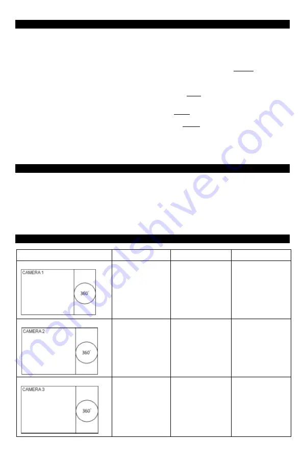


  PATTERN DESCRIPTION 


Pattern 

Preset Cruise 

Preset Sequence 

Motion Tracking 

MODE 1 


Yes 

Yes 

Yes 

MODE 2 


Yes 

Yes 

Yes 

MODE 3 


Yes 

Yes 

Yes 

Summary of Contents for HD5FE-8012

Page 1: ...amera USER MANUAL FEATURES SDI 1080P 1920 x 1080 SDI HDMI 4 Channel CVBS Output 1 3 2 Color CMOS QSXGA 5 Megapixel 1 19mm Megapixel Lens Built in Microphone 12V DC 550mA max Please read the Manual bef...

Page 2: ...specifications Camera must be connected to a surge protector at all times 6 Objects and liquid entry Never push objects of any kind into this camera as this may touch dangerous voltage points of short...

Page 3: ...ng Metal Bracket Holders 5 Four 4 Wall Mounting Screws 6 Four 4 Wall Anchors 7 Four 4 Washers 8 One 1 Wall Mount Template 9 One 1 User Manual DIMENSIONS Unit inches mm For any returns please include a...

Page 4: ...amera 2 The camera uses the SDI connector output or the HDMI connector to a HD SDI monitor that doesn t have RS485 built in connector The user link the 2 RS485 wire from the camera to a keyboard contr...

Page 5: ...is on PELCO D and baud rate 9600 And the control command is same as usual Command The screen mode default is on mode 5 It displays in 5 windows quad 360 Camera 1 4 is virtual split from 360 screen Us...

Page 6: ...Select the camera and 360 It depends on SDI connect to which channel If camera is on channel 1 please make sure the address is from 1 to 4 And choose protocol is PELCO D baud rate is 9600 Please go to...

Page 7: ...means that camera can adjust the mode automatically after a period of time 5 10 or 15 seconds SHOW MODE WALL 0 WALL 90 WALL 180 WALL 270 DESK CEILING Select the desired mode and then press enter butto...

Page 8: ...TEM CAMERA1 ON OFF CAMERA2 ON OFF CAMERA3 ON OFF CAMERA4 ON OFF AUTOFLIP ON OFF SETID If user plans to have more than 1 device in the installation LOAD DEFAULT Will reset the device to factory default...

Page 9: ...motion detection will be disabled Osd will display on screen SCAN Call preset 76 run the auto pan function Osd will display on screen TOUR This function is also available on the keyboard by pressing...

Page 10: ...10 MODE 4 Yes Yes Yes MODE 5 Yes Yes Yes MODE 6 Yes Yes Yes MODE 7 No No No MODE 8 No No No MODE 9 No No No MODE 10 Yes Yes Yes...

Page 11: ...Video 1 Yes Only cam 1 Not Recommended 5 Yes Cam 1 2 3 4 Recommended 2 Yes Only cam 2 Not Recommended 6 Yes Only cam 1 3 Not Recommended 3 Yes Only cam 3 Not Recommended 7 13 No Not Recommended All bl...

Page 12: ...2 Cut hole for I O Connection Cable Step 3 Hammer the 4 wall anchors into the holes Step 4 Place 4 washers on the 4 mounting screws Step 5 Screw bottom base to wall In Ceiling Mount Step 1 Twist main...

Page 13: ...driver and turn clockwise The small will hit the small plastic stick of the mold until it fits the thickness of the ceiling Do the same for the 2 other screws Note 1 There are no actual holes on the c...

Page 14: ...ontal 185 Vertical 185 Gamma Correct 0 45 1 RS485 PELCO D 9600 Video Output SDI HDMI 4 Channel CVBS Lens 1 19mm Megapixel Lens F2 0 ICR Built in Format 1080P Power Source 12V DC Jack 10 1A Power Consu...

Page 15: ...15...

Page 16: ...16 www okinausa com MADE IN TAIWAN www okinausa com HDC 39 Copyright 2014 All Rights Reserved R201402 V19...

Reviews: