


89
Item No.
2
3
Items
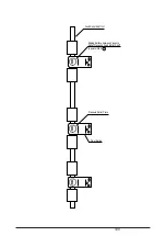
AG Plate Gap
Auto Gap Correction
Standard Value
C=0.14
±
0.02mm
Illustration
3
Turn on the printer while pressing
Switches
B
and
C
.
4
The auto gap correction has completed
if “Av” is printed.
Adjustment Method
1
Insert the thickness gauge between
the AG frame and the AG plate to veri-
fy the gap value C is between 0.12 and
0.16 mm.
2
If adjustment is required, screw down
the mounting screws and adjust the ec-
centric collar to make the protector gap
value C between 0.12 and 0.16 mm,
then fix the AG plate.
Notes:
After this Adjustment, the Auto Gap
Correction should be conducted (See
item 3)
1
Set the continuous form (1P, 15 in.
wide and 55 Kg) at the printing valid po-
sition and also the ribbon cassette.
2
Turn off the printer, then power on
again while pressing Switches
B
and
C
to conduct the auto correction. If the
auto gap operation has been repeated
3 times and “Av= “ printed, it is the
end of the auto gap correction.
3
The auto correction value from 09 H
to 18 H is desirable. If any value other
than this is indicated, the AG plate gap
should be adjusted again. (See Item 2)
Notes:
a) In the following cases, this adjust-
ment should be implemented.
i)After the gap adjustment between the
AG frame and the AG plate;
ii)After replacing the control board. (not
required after CG/PROGROM, EE-
PROM replacement)
b) When the correction value “Av= “ is
not between 09 and 18, “Warning” will
be indicated on the LCD panel. Press
Switch 1 to reset this warning.
c) The correction value “Av= “ from
09 to 18 is desirable. If any value oth-
er than this is indicated, the gap bet-
ween the AG frame and the AG plate
should be adjusted again to the prop-
er range as described in Item 2.
Then, conduct this correction.
C
AG Frame
AG Plate
Eccentric Collar
Carriage Frame
Mounting Screws
PARK
TEAR
PATH
ONLINE
RESET
GROUP
POWER
ALARM
ITEM OPTION
MENU
STORE
TOF
SHIFT
O N - L I N E E P S
F R O N T F E E D
CONFIG
LF
MicroFeed
Down
FF/LOAD
MicroFeed
Up
1
2
3
4
5
6
7
8
9
0
A
B
C
1
2
3
1st = 0EH
2nd = 0DH
3rd = 0EH
AVE = 0EH
Summary of Contents for PACEMARK 4410
Page 2: ...1 PACEMARK 4410 PRINTER Service Manual...
Page 53: ...52 Figure 3 1 3 2 Parts Layout...
Page 96: ...95...
Page 152: ...151 No Yes End Replace PHA Board Recovered No Yes End Replace PMA Board...
Page 180: ...120 Knob Assy 40782001 8 4 6 3 5 10 7 1 2 9...
Page 182: ...122 Ribbon Assy Feed 40506101 1 15 8 7 8 14 6 5 10 13 3 4 13 2 6 7 14 9 11 11 1...
Page 184: ...124 Sprocket Assy L 40507601 3 2 5 6 1 19 19 7 4 21 10 8 9 20 18...
Page 186: ...126 Sprocket Assy R 40508101 3 7 11 11 1 6 5 2 13 4...
Page 190: ...130 Sheet Feeder Assy R Rear 40509101 8 11 1 9 4 13 13 10 6 5 2 9 12 7 3 Pin Protrusion...
Page 196: ...136 Front Cover Assy 40677201 ODA 40677202 OEL 10 6 9 9 9 2 4 4 1 3 7 7 5 9 10 10 6 6...
Page 198: ...138 Rear Cover Assy 40678301 11 6 5 9 10 10 8 10 10 10 9 4 1 10 3 2 7 13...
Page 202: ...142 Frame Assy OpePane 40755801 3 2 4 6 8 9 9 1 5...
Page 204: ...144 PMA PDA PCB Assy 40752201 4075202 4 or 6 5 or 7 1 or 2 3 8 9 11...