background image


152

F

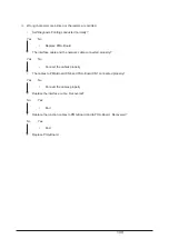
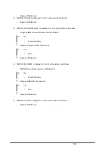
Printer operates normally but characters are not printed.  (With Option Serial Board used)

• Self Diagnosis Printing conducted normally?

Yes No

• Replace PMA-Board.

• The interface cable connected properly?

Yes No

• Connect the cable properly.

• The serial interface setting adjusted for the system?

Yes No

• Set it properly.

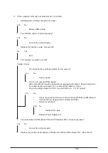
• Replace the interface cable.  Recovered?

No Yes

• End

• With Menu, check Printer’s recognition of PAA-Board, the Option Serial Board attachment.

At Menu Setting, select “Set-up” as Group and “Host Interface” as Item.  If “Opt. Card” is displayed
in Set Window, Printer recognizes PAA-Board.

• PAA-Board recognized by Printer?

Yes No

• PAA-Board and PMA-Board connected properly.

Yes No

• Connect them properly.

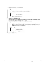
• Replace PAA-Board.

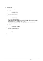
• With Menu, check Printer’s recognition of Option Serial Board.

At Menu Setting, if “Serial I/F (OP)” is displayed as Group, Printer recognizes Option Serial
Board.

Summary of Contents for PACEMARK 4410

Page 1: ...Thank You for purchasing this Factory Service Manual on EBAY from PCTECHINFO Click Here for more Factory Service Manuals for other Computer and Printer Copier Manufacturers from PCTECHINFO...

Page 2: ...1 PACEMARK 4410 PRINTER Service Manual...

Page 3: ...s maintenance manual describes how to maintain the Pacemark 4410 printer in the field This manual is for customer engineers For further information refer to the Users Manual for handling or operating...

Page 4: ...33 2 2 Mechanical Operation 34 2 2 1 Printhead mechanism and operation 34 2 2 2 Spacing operation 36 2 2 3 Head gap adjusting 37 2 2 4 Ribbon drive 40 2 2 5 Paper Feed Mechanism 41 2 2 6 Bail Feed Me...

Page 5: ...3 3 25 Knob Bracket Assy 78 3 3 26 Space Belt 79 3 3 27 AG Sensor Frame Start Searching Sensor 80 3 3 28 Paper Jam Sensor Assy Bail PE Sensor Assy 81 3 3 29 Sprocket Assy L R Front Tractor 82 3 3 30...

Page 6: ...sor PCB RS232C I F IEEE 1284 I F Bail motor Tractor change motor LF motor Head FAN Bail position SW Tractor change SW Front PE SW Rear PE SW Paper jam sensor Paper top sensor AG sensor coil LCD Operat...

Page 7: ...sm Main control Motor driver board Head driver board Interface Motor Sensor board including IEEE 1284 bidirectional parallel interface and RS 232C serial interface Motor Sensor and AG sensor boards Op...

Page 8: ...7 1 3 Option Specifications Options available for the Pacemark 4410 are as follows 1 Interface boards a Okilan 6100e Network card...

Page 9: ...r 9 to 14 lbs with front feed Carbon paper Four sheet maximum including original 34 g m2 9 lbs with rear feed When 7p or more papers are used for the front tractor High Impact Copy should be selected...

Page 10: ...meter 0 36mm 0 014inch 8 Line feed Speed 6 LPI spacing one LF 60 ms 8 LPI spacing one LF 52 ms Continuous paper feed rate is 15 inches per second at head gap 1 2 9 Line Feed Pitches 6 LPI 0 167 inch 4...

Page 11: ...mode ISO 7779 15 Ribbon Genuine OKI cartridge ribbon Ink color Black Ribbon life Approximately 15 million characters Characters in Utility mode 16 Reliability a MTBF mean time between failures 12 000...

Page 12: ...circuit 1 Microprocessor IC24 80C186 16 This processor is a CMOS single chip computer with integrated peripheral device functions and a 16 bit MPU core The processor has a 20 bit address bus and a 16...

Page 13: ...OWDOWN P AC DOWN P POW ONRST N POWALM P CG ROM 4M PRG ROM 4M Slit sensor IEEE1284 BUF BUF BUF OPpanel OPpanel LSI DRAM 4M RS232 LSI D R EEPROM LCD HEAD Head driver AG sensor Ribbon motor driver SRAM 1...

Page 14: ...e program ROM is assigned to the program memory area of the MPU and is fetched by the RD signal of the MPU The following shows the operation of the memory access Figure 2 2 MPU CLOCK ALE A16 BHE AD0 A...

Page 15: ...eceiving buffer printing buffer DLL buffer and working buffer The following shows the examples of the memory access operation MPU CLOCK ALE A16 BHE AD0 AD15 RD AD0 AD15 WR CS AD0 AD15 A16 BHE DRAMD0 D...

Page 16: ...CG ROM is assigned to the program memory area of the MPU and is fetched by the RD signal of the MPU The following shows the memory access operation MPU CLOCK ALE A16 BHE AD0 AD15 RD CS AD0 AD15 A16 BH...

Page 17: ...eration Figure 2 5 NHDC LSI EEPROM EEPROMWR P EEPROMCS P EEPROMRD P EEPROMCLK P DI CS DO SK Ready Bus twp D0 D15 A0 A5 1 1 0 Start code Operation code Address Data tCS PRE O PE Address Start code Oper...

Page 18: ...rint head c Space motor speed control function It controls the space motor with micro programs to accelerate decelerate it This LSI also controls the speed of the space motor in agreement with each pr...

Page 19: ...18 Figure 2 6 MPU CLOCK ALE A16 BHE AD0 AD15 RD AD0 AD15 WR CS AD0 AD15 A16 BHE MPU Main LSI A16 BHE A0 A15 D0 D15 A0 A15 D0 D15 ALE RD WR CS CLK...

Page 20: ...er e External interface It controls various interfaces for main LSI IEEE1284 serial MUPIS OpePaneLSI EEPROM f Motor drive interface Each control of OVDV pulse generation for AG motor generation of pul...

Page 21: ...MPU The program here sets the mode of the LSI including the MPU checks the memories ROMs and RAMs then carries out carriage homing and determines the LF motor phase Finally the program establishes the...

Page 22: ...Interface Control The Parallel data input from the host to the NHDC LSI is latched to its internal register at the falling or rising edge of the STROBE N signal At the same time the LSI sets the BUSY...

Page 23: ...to the serial I F LSI and NHDC LSI The serial I F LSI converts serial data into parallel data to output it to the MPU Output signals DTR RTS SSD and TD to the serial I F are output from the MPU to th...

Page 24: ...start position printing speed etc to the LSI and activates the spacing motor The MPU when the carriage arrives at the print position specified activates the printer to start printing and when printing...

Page 25: ...etermination inside the LSI 1 Correction for the number of pins driven The driving time is corrected according to the number of pins driven at the same time out of 18 pins 2 Correction according to ad...

Page 26: ...25 Figure 2 12 Dot magnet drive coil current DT1 signals D1 D18 DT2 signals D1 D18 DT2 Basic drive time 1 2 3 DT1 Basic drive time 3...

Page 27: ...rature compensation See2 1 14 Alarm Circuit d Print mode compensation According to the thickness of the printing medium the print mode is compensated as shown in the table below Head Gap Range 1 2 3 4...

Page 28: ...enerate head drive timing 2 1 11 Line feed The LF motor is locked by the current supplied from 12V according to the pulse duty of the LFCHOP P signal during the stop period It is driven by 44V applica...

Page 29: ...12 Bail tractor switching AG ribbon motor control Bail tractor switching AG and ribbon motor control is as shown below The AG motor is locked with AGHOLD P MO 1 MO 2 MO 3 MO 4 MO OVDV AGHOLD P Figure...

Page 30: ...e OPSCLK N signal The LSI decodes this command and when it is found to be legal returns a 2 byte command response back to the NHDC LSI which includes data on Switch information LED status LCD status r...

Page 31: ...decoding the command OPDATAOUT P OPSCLK N OPDATAIN P OPSQCR N 1 2 3 2 3 1 6 7 5 or 8 bit0 bit7 Command first Command second Command response first Command response second Note bit0 bit7 Reset within...

Page 32: ...it rises when the potential goesabovethealarm1specificlevel MPUgoesintoalarm1procedure simultaneouslyMPU continues to check if the potential goes above alarm 2 specific level When going below alarm 2...

Page 33: ...h line to cool down the printer When the temperature becomes lower than the specified normal printing will be resumed 8 Fuse alarm circuit Fuses are mounted on each of the SP motor and the other pulse...

Page 34: ...of an abnormal temperature rise in the power supply circuit or an overcurrent of 44V The control unit suppresses the overcurrent by two pass printing If the output does not change the power supply cir...

Page 35: ...unit is connected to the control circuits through the control board Figure2 20 Arrangement of the head pins View from the tip of the printhead 1 The printhead configuration The printhead is composed...

Page 36: ...enerate in the opposite direction against that of the permanent magnet and a restoring force of the armature in the opposite direction against the core and then the print wire impinge on the platen Th...

Page 37: ...When the DC servo motor runs clockwise as viewed from its front side the driving force is transmittedtotheminipitchbeltandthecarriagemovesfromthelefttotheright TheDCservo motor rotating angle and spe...

Page 38: ...pen position As the off line mode is released shifted to on line after platen reverses the AG motor drives the platen to the direction that the space between the print head and platen becomes narrower...

Page 39: ...direction of platen Platen Bearing Cam roller Core Coil EI sensor Sensor frame Deflecting direction of sensor frame AG press plate Carriage frame Platen Platen Bearing Cum roller AG motor pulse motor...

Page 40: ...39 3 AG detector detail drawing Head AG plate Paper AG sensor flame Core gap AG plategap Ferrite core Figure 2 25...

Page 41: ...2 Feeding The ribbon feeding mechanism starts running regardless of whether the printer is printing or not and stops at the same time when the spacing motion stops When the ribbon motor is driven the...

Page 42: ...ear and front tractor drive gear driving the pin belt of the front tractor Assy This feeds a continuous paper set on the pin belt Simultaneously this drives the feed roller F R through the mini pitch...

Page 43: ...n wheel and pin belt of the tractor Assy This feeds a continuous paper set on the pin belt Simultaneously this drives the feed roller F R through the mini pitch belt following LF gear to carry the pap...

Page 44: ...gears so that the change gear moves transversely If the change gear is shifted to right the rotational force is transmitted to the front tractor gear driving the front tractor If the change gear is sh...

Page 45: ...44 Front drive shaft Front tractor drive gear Change gear LF gear Rear tractor drive gear Change motor Change lever Rear drive shaft Rear tractor drive Front tractor drive Figure 2 30...

Page 46: ...se position This position is for the condition where a paper is being printed and carried with both bail Assy and feed roller front upper closed 2 Bail open position This position is for the condition...

Page 47: ...46 i Close position ii Open position iii Half open position Half open Open Open Close Close Close Cam Bail lift pin Bail lift lever Figure 2 32...

Page 48: ...et to the ON state When the form runs out the paper end lever comes into the hole on the sheet feeder cover rib and the bottom of the paper end lever leaves the microswitch to turn it off for form end...

Page 49: ...48 3 Rear tractor Form Sheet feed cover rib Pin tractor L Paper end lever Micro switch Figure 2 34 Rear form end detection mechanism...

Page 50: ...le of installation follow the instructions 3 PARTS REPLACEMENT The section explains the procedures for replacement of parts assemblies and units in the field Only the removal procedures are explained...

Page 51: ...nt head Printer Unit Disassembly prohibited parts Print head Space motor Ribbon pulse motor Autogap motor Tractor change motor Bail motor Eccentric collar L R within the bearing on the adjusting cam G...

Page 52: ...ools No No 1 100 Philips screwdriver Q ty Place of use Remarks Service Tools 1 2 3 4 5 6 8 No 2 250 Philips screwdriver Magnetized No 3 100 screwdriver No 5 250 screwdriver Digital multimeter Pliers 1...

Page 53: ...52 Figure 3 1 3 2 Parts Layout...

Page 54: ...53 3 3 How to Change Parts This section explains how to change parts and assemblies appearing in the disassembly diagram below...

Page 55: ...ing it to the arrow direction 4 Unscrew 4 screws A and the screw B 5 Release Hooks C then remove Cover Assy Front D and Door Assy Front E 6 Unscrew 4 screws F then lift and remove Frame Assy Rear G 7...

Page 56: ...lug the connector to Power Supply Assy 6 and unscrew 2 screws 8 then remove FG Wires 9 5 Unplug Junction Board Cord 0 from Junction Board PRA Printed Board CN1 6 Unplug SP Slit Sensor Cord A 7 With th...

Page 57: ...ol Board PMA Printed Board and Driver Board PDA Printed Board Unscrew 2 screws 3 then pull Driver Board PDA Printed Board 4 upward and release it from the connecting position to Control Board PMA Prin...

Page 58: ...ward the protrusion on Power Supply Unit 1 and sliding it in the arrow direction through 2 inserting positions remove Power Supply Unit 6 For installation reverse the removal procedure Note on Install...

Page 59: ...n Board PRA Printed Board CN13 1 3 Unscrew 2 screws 3 and remove PG Cooling Fan 4 4 For installation reverse the removal procedure Note on Installation 1 Mount the fan to produce wind in the direction...

Page 60: ...d remove Cable Holder 2 3 Unscrew 2 screws 3 and remove I F Board Holder Cover 4 4 Unplug all the connectors to I F Board PHA Printed Board 5 5 Unscrew the screw 6 and 4 screws 7 then remove I F Board...

Page 61: ...hen remove AG Board PGA Printed Board 3 and unplug AG Slit Sensor Cord 4 6 For installation reverse the removal procedure Note on Installation 1 The distance to Slit Disk should be 0 5 mm or shorter 2...

Page 62: ...nd remove Bail Gear Assy 2 3 Unscrew 2 screws 3 and remove AG Motor Assy 4 4 Unscrew 2 screws 5 and remove Motor 6 5 Remove Idle Gear 7 and Tractor Idle Gear 8 6 For installation reverse the removal p...

Page 63: ...ront stuck See 3 3 1 2 Unscrew 2 screws 1 and remove Shaft Support Plate press fit 2 3 Screw down the screw 3 and turn Idle Pulley Assy 4 into the right direction 4 Remove Mini Pitch Belt 5 5 For inst...

Page 64: ...ee 3 3 6 4 Release the cords from Cord Clamp 3 on the cord route 5 Unscrew 2 screws 4 and remove Cable Holder 5 6 Unscrew the screw 6 and cut the wrapping tie 7 7 Remove Micro Switch 8 8 Unscrew 2 scr...

Page 65: ...3 Unplug the connectors A from I F Board PHA Printed Board CN11 B 4 Release the cords from the cord clamps on the cord route 5 Unscrew the screw 2 and cut the wrapping tie 6 Remove Micro Switch 3 7 Un...

Page 66: ...ck See 3 3 1 2 Remove I F Board See 3 3 6 3 Remove Printer Unit See3 3 2 4 Remove Tractor Change Motor Assy See3 3 10 5 Unscrew 3 screws 1 and remove LF Motor 2 6 For installation reverse the removal...

Page 67: ...d PRA Printed Board CN6 6 3 Release the cords from the cord clamps on the cord route 4 Unscrew 2 screws 2 and remove SP Motor Fan Assy 3 5 Unscrew 2 screws 5 and remove Head Cooling Fan 1 5 6 For inst...

Page 68: ...lder Cover 2 3 Unplug the connector 3 from I F Board PHA Printed Board CN6 6 4 Release the cords from the cord clamps on the cord route 5 Unscrew 2 screws 4 and remove Head Cleaning Fan 2 5 6 For inst...

Page 69: ...he clamps on the cord route 9 Unscrew 1 screws C and remove FG Mesh 3 10 Unscrew 4 screws A and remove Space Motor 6 11 For installation reverse the removal procedure Note on Installation 1 After asse...

Page 70: ...or Board POA Printed Board CN1 1 3 Unscrew 2 screws 3 and Remove Operator Block Assy 4 4 Unplug the connector 8 from Operator Board POA Printed Board CN2 1 5 Unscrew 3 screws 5 and release 3 claws the...

Page 71: ...ame Assy Rear Plate Front stuck See 3 3 1 2 Unplug the connector 1 from Junction Board PRA Printed Board CN9 7 3 Unscrew 2 screws 2 and remove Ribbon Feed Assy 3 4 Release the cord wrapping tie 4 and...

Page 72: ...e right seen from the front 3 Pull out Ribbon Guide 1 upward 4 Unscrew 2 screws 2 and remove Printhead 3 from the connector 5 For installation reverse the removal procedure Note on Installation 1 The...

Page 73: ...nnector green 4 7 Unscrew 2 screws 5 and remove Head Cable Cover 6 8 Unplug Head Cable 7 pulling it to the left 9 For installation reverse the removal procedure Note on Installation 1 When the head ca...

Page 74: ...screw 4 and remove Paper Width Sensor 5 5 Unplug the connector 6 6 Remove 2 Ribbon Guide Posts 7 and 2 washers 8 7 Remove Ribbon Protector 9 8 For installation reverse the removal procedure Note on I...

Page 75: ...move Printer Unit See 3 3 2 3 Unscrew 2 screws 1 and unplug the connector 2 from Junction Board PRA Printed Board CN12 4 then remove Space Motor Fan 3 4 For installation reverse the removal procedure...

Page 76: ...Cover Assy Front Frame Assy Rear Plate Front stuck See 3 3 1 2 Unplug all the connectors from the above 3 Unscrew 2 screws 1 and remove Junction Board PRA Printed Board 2 4 Unscrew 3 screws 3 and remo...

Page 77: ...racket 3 4 Unplug the connector 4 from Junction Board PRA Printed Board CN4 8 then remove Cover Open Switch Assy Ribbon Rotation Sensor 5 5 Unscrew 2 screws 6 and remove Cover Open Switch Assy 7 6 For...

Page 78: ...cables 1 3 Unscrew 2 screws 2 and remove Interlock Switch 3 4 Unplug 6 connectors 8 5 Unplug connectors 4 to Spacing motor code 5 6 Unplug Interlock Switch Cord Assy 7 from the cable clamp 7 For inst...

Page 79: ...Knob Bracket Assy 4 4 Unscrew 2 screws 5 and remove AG Sensor Cover 6 5 Unscrew the screw 7 and remove Knob Cover 8 6 Remove the E ring 9 Gear 0 and Adjusting Knob A 7 Remove Spring Pin B then remove...

Page 80: ...2 Remove Space Motor See 3 3 15 3 Remove Printing Head See 3 3 18 4 Remove Idle Pulley 1 from Idle Pulley Bracket then remove Space Belt 2 5 Unscrew 5 screw and pull out Connector Guide 3 unscrew the...

Page 81: ...ase the latch then remove Start Searching Sensor Lever Assy 9 and Start Searching Sensor Cord 0 together 6 Unscrew the screw A and unplug the connector B from I F Board CN9 then unplug Start Searching...

Page 82: ...te Front stuck See 3 3 1 2 Unscrew the screw 1 and release the latch then remove Paper Jam Sensor Assy 2 3 Unscrew the screw 3 and release the latch then remove Bail PE Sensor Assy 4 4 Unplug the conn...

Page 83: ...ove the Snap Band 7 Release the claw to remove Front Tractor Drive Gear 4 8 Pull out Front Tractor Drive Shaft 5 to the right 9 Unscrew 2 screws 6 and remove Front Lock Shaft 7 Sprocket Assys L 8 and...

Page 84: ...ft D with Sheet Feeder Assy L Rear 8 and Sheet Feeder Assy Rear R C on 11 Release Lock Lever E and remove Sheet Feeder Assy L Rear 8 and Sheet Feeder Assy Rear R C from Lock Shaft D 12 For installatio...

Page 85: ...84 2 A 6 7 4 2 B 5 8 3 D 1 E E F 9 C B Align the hole positions When mounting Releasing the Gear latches Wave Eling Washer Bush Drive shaft R Side View...

Page 86: ...drive gearB and install 2 drive gear B to 5 3 rear drive shaft of the rear tractor Assy at a position where the directions of marks on 4 drive gear B and 2 rear tractor drive gear match 8 Assembling f...

Page 87: ...and Drive Gear C 8 to the oblique upper direction and remove Bearing Bail 0 8 Remove 2 Bail Springs A 9 Remove Screw Stud B 10 Slide Bail Support Shaft C to the right then remove it from left Bearing...

Page 88: ...2 200 screwdriver Feeler gauge 500 g rod tension gauge Calipers Adjustment should be conducted after removing the Rear Cover B and setting the Dip Switch 1 on the board to ON maintenance mode See Note...

Page 89: ...mm Notes Although the adjustment should use a range from 0 12 to 0 16mm the configura tion should use a range from 0 09 to 0 2mm 2If adjustment is required screw down the ribbon guide post with the Ph...

Page 90: ...is the end of the auto gap correction 3The auto correction value from 09 H to 18 H is desirable If any value other than this is indicated the AG plate gap should be adjusted again See Item 2 Notes a...

Page 91: ...icated on the LCD The cover should be closed during this process Notes In the following cases this adjustment should be implemented 1 After replaceing the Control board not required after ROM replacem...

Page 92: ...idle gear and the adjusting cam 1Verify the backlash is 0 2 mm bet ween the idle gear A and the drive gear B and between the idle gear B and the idle gear C 2If adjustment is required screw down the...

Page 93: ...iage Notes 1 To prevent the float of head when tight ening the screws Notes 2 Tightening the screws while pressing the head in the direction of 3Adjust the backlash of screws so that the print head ca...

Page 94: ...mber 5 4 3 2 1 0 1 2 3 4 5 Correction dot position of reverse printing Printing position is shifted by 0 25mm to right of the reference position Printing position is shifted by 0 20mm to right of the...

Page 95: ...ly lubricating oil to that portion after cleaning 1 Cleaning time When the equipment time has reached six months or 300 hours whichever comes first 2 Cleaning tools Dry cloth soft cloth such as gauze...

Page 96: ...95...

Page 97: ...Remove the dust on the Sensor Ribbon Jam Sensor Remove the dust on the Sensor Paper Out Sensor Remove the dust on the Sensor Paper Jam Sensor Remove the dust on the Sensor 2 Lubricant Pan motor oil o...

Page 98: ...urfasce GEP A Gear Teeth Surfasce GEP A Shaft PM B 2 points at left and right Bail Lift Lever Rack GEP A at left and right Sliding Surface between Feed Shaft Bearing and Side Frame at upper and lower...

Page 99: ...am Surface GEP A at left and right Idle Pulley Shaft PM B Shaft PM B 3 points at left and right Shaft PM B 2 points at left and right Gear Teeth Surface GEP A Gear Teeth Surface GEP A Sliding Surface...

Page 100: ...99 Sliding Surface between Platen Slide Plate and Platen TEP A 2 points at upper and lower Platen Slide Plate Platen Side Frame...

Page 101: ...100 Sliding Surface between Pressure Roller Piece and Feed Roller Shaft 3 points GEP A Feed Roller Shaft FU Pressure Roller Piece Front Spring...

Page 102: ...Surfasce GEP A Between bush and Shaft PM B Between bush and Shaft PM B Between Gear and Shaft PM B Between Gear and Shaft PM B Between Gear and Bracket GEP A Between Gear and Bracket GEP A Gear Teeth...

Page 103: ...ints Apply a small amount of Albania grease on the teeth surface of the rack GEP B both right and left Apply a small amount of Albania grease on the stud sliding surface All periphery GEP B both right...

Page 104: ...103 Apply a small amount of Albania grease on the stud sliding surface GEP B both right and left...

Page 105: ...tailed flowchart 5 Carry out a thorough test after the repair to check for correct functioning 6 2 Troubleshooting Table Table 6 1 Status Details Flowchart item No Trouble upon power on Power is not s...

Page 106: ...is in the self test mode Indicates that the printer is in the menu mode Front form end Rear form end Paper Eject Jam Paper Load Jam Paper Park Jam Paper Feed Jam Paper Jam RIBBON FEED JAM ON LINE HEX...

Page 107: ...t Access Cover is opened Indicates that Cover Open Alarm occurred when data remained inside Cover Open during space system operation then Cover was closed For details see paragraph 2 fault alarm displ...

Page 108: ...A I L Error Category LCD Comments Remedies RAM ALARM ROM ALARM PROGRAM ALARM ENGINE ALARM D RAM Error S RAM Error Program ROM Error CG ROM Error EEPROM Error Watch Dog Time Error Invalid Input Error S...

Page 109: ...egory LCD Comments Remedies ENGINE ALARM OPERATION PANEL ALARM FLASH MEMORY ALARM MUPIS ALARM OPTION ALARM Ribbon Motor Error Paper Width Sensor Error LCD Time out Error Flash Memory Chip Error Except...

Page 110: ...sitions PRA AC Inlet PGA POWER SUPPLY UNIT PMA PDA PHA Control Block Assy Operation Panel Assy Interface Assy LCD UNIT Option Board POA CN2 CN13 CN6 CN4 CN2 CN5 CN2 CN1 CN1 CN4 CN2 CN12 CN9 CN8 CN10 C...

Page 111: ...bbon Motor RibbonJam Sensor Interlock Switch SP Motor Space Slit Sensor PGA PCB Auto Gap Slit Sensor Auto Gap Motor Connector to Auto Cutter Unit Rear Tractor Sheet Jam Sensor Bail Paper End Sensor Re...

Page 112: ...1 09 N HDT20 09 P HDT1 10 N HDT20 10 P HDT1 11 N HDT20 11 P HDT1 12 N HDT20 12 P HDT1 13 N HDT20 13 P HDT1 14 N HDT20 14 P HDT1 15 N HDT20 15 P HDT1 16 N HDT20 16 P HDT1 17 N HDT20 17 P HDT1 18 N HDT2...

Page 113: ...bout 1 08 PMA PCB CN6 49 65 57 53 67 61 6 2 4 5 1 3 6 2 4 5 1 3 50 66 58 54 68 62 CN1 CN13 LF M0 PHA PCB LFDV1 LFCOM LFDV3 LFDV2 LFDV4 PMA PCB 46 48 50 PRA PCB Inter lock switch CN10 CN2 SP FOW SP REV...

Page 114: ...DV2 RBN MDV4 PMA PCB PDA PCB CN6 58 66 62 59 63 4 5 2 3 6 1 1 5 3 4 6 2 57 65 61 60 64 CN1 CN7 PATH CHANGE M0 PHA PCB TR MDV1 TR MCOM TR MDV3 TR MDV2 TR0VDV N TR MDV4 TR MCOM TR0VDV N CN1 CN1 Path cha...

Page 115: ...IL M0 PHA PCB BEIL MDV1 BAIL MCOM BEILMDV3 BAILMDV2 BEIL MDV4 8 Space Fan1 PMA PCB CN2 2 1 3 7 5 1 4 7 5 1 4 CN1 CN12 PRA PCB SPFANDV P SPFANALM1 P SG Space Fan1 9 Space Fan2 PMA PCB CN9 2 1 3 SPFANDV...

Page 116: ...PCB CN2 2 1 3 11 9 1 4 11 9 1 4 CN1 CN13 PHA PCB POWFANDV P POWFANALM P SG Power Fan 13 space slit sensor PMA PCB CN8 4 2 1 5 3 4 2 1 5 3 Slit sensor 5V PHA P PHB P SG SPTH P 14 Auto gap slit sensor P...

Page 117: ...cal Sensor PMA PCB CN1 9 7 10 8 5 6 3 4 2 1 NC NC NC NC NC NC 66 19 30 32 65 64 63 33 34 66 19 30 32 65 64 63 33 34 CN5 E A C K PDA PCB WITHSNS P SNS5V 1 SG RIBONOUTSW P LINSNSPHA P LINSNSPHB P 5V CN1...

Page 118: ...paper end sensor Paper jam sensor 19 Bail Open Switch Front Tractor On Switch PMA PCB CN6 44 54 45 1 3 5 43 53 46 2 4 6 4 3 2 1 6 5 CN1 CN1 NC NC NC C NO PHA PCB BEILOPNSW P FTRONSW P COVEROPN0SW P S...

Page 119: ...22 Power Supply Unit 1 3 4 6 7 8 9 10 11 12 13 1 6 7 12 1 6 7 12 44V EP 44V EP AC L FG AC N AC L FG AC N 1 3 6 12 7 8 9 10 11 12 13 SG EP 12V 12V POWALM P POWOFF P POWONRST N POWDWN P ACDWM P SG EP 1...

Page 120: ...SG 5V 4V RS R W E DB4 DB5 DB6 DB7 BL5V CN2 38 26 28 30 32 36 34 4 1 3 5 37 25 27 29 31 35 33 3 2 4 6 1 2 3 4 5 6 7 8 9 10 SHIFTSWON N OPSCLK N OPDATAOUT P OPDATAIN P OPQCR N BZON P 5VD 5V SG SHIFTSWO...

Page 121: ...TA7 P DATA8 P ACK N BUSY N PERROR P SELECT P AUTOFD N SG PLOGIC H INIT N FAULT N NC IF H SELECTIN N TXD SSD RTS DTR RXD CD CTS DSR SG FG NC 1 2 3 4 5 6 7 8 9 10 11 12 13 14 15 16 33 19 30 17 37 38 18...

Page 122: ...121 25 Short Plug 1 2 3 T1 5V IC45 BYTE IC47 BYTE PGROMCS H 1 2 3 T2 NC CNIF H 5V 10K 1 10W 3 3K 1 10W 1 2 3 T3 5V PGROMSEL N SG 10K 1 10W 1 2 3 T4 5V CNPLOGIC H 5V 3 9K 1 10W 100 1 4W...

Page 123: ...DVREV3 P DVREV2 P DVREV1 P DVREV0 P POWEROFF P 44VF 12V EP 44V 12VR DVREV3 P DVREV2 P DVREV1 P DVREV0 P 62 68 69 70 20 21 35 40 75 73 74 76 80 71 72 25 24 23 22 PMA PCB PDA PCB CN1 CN1 PMA PCB PRA PC...

Page 124: ...P MPSA06 P MPSA07 P MPSCE N MPSDECORD1 P MPSCUREQ N MPSOPREQ N OPDCT0 N NC OPDCT1 N NC NC MUPISARI N 5V 0V MPSD04 P MPSD12 P MPSD11 P MPSD05 P MPSD13 P MPSD06 P MPSD14 P MPSD00 P MPSD15 P MPSA00 P MP...

Page 125: ...B19 B20 B21 B22 B23 B24 B25 B26 B27 B28 B29 B30 B31 B32 NC NC NC NC NC PE N ACK N SIFSEL N NC BUSY P IFDATA4 P IFDATA3 P NC IFDATA5 P IFDATA2 P IFDATA6 P NC IFDATA1 P IFDATA7 P IFDATA8 P NC SIFRST P R...

Page 126: ...IFDATA5 P IFDATA2 P IFDATA6 P IFDATA1 P IFDATA7 P IFDATA8 P SIFRST P RSTIN P SIFSTB N SIFON N SIFRD N CNBARI N NC SG NC NC NC NC NC NC NC NC NC NC NC NC NC NC NC NC NC NC NC NC NC NC NC RST N 12V 12V...

Page 127: ...8 A10 A11 A12 A14 A15 A16 A18 A19 A20 A22 A23 A24 A26 A27 A28 A29 A5 A9 A13 A21 A25 A2 A4 A5 A8 A10 A12 A14 A20 A22 A24 A26 A32 5V D03 D10 D12 D09 D01 D08 D07 RD N A08 A01 A02 A03 A04 A05 A06 A07 CE N...

Page 128: ...r Cutter Option 39 41 43 44 31 29 27 25 23 21 19 1 4 39 41 43 44 31 29 27 25 23 21 19 1 4 9 8 7 6 5 4 3 2 1 EP 44VF CUTMOYDV P CUTM1 P CUTM2 P CUTM3 P CUTM4 P RENCUT N SG PMA PCB PRA PCB CN2 CN1 CN8 C...

Page 129: ...ard outside without unplugging the cables Stop sliding when the cables becomes straight Do not extend the cables by force Check the voltage between Control Block C75 side and GND1 or GND2 Yes No The c...

Page 130: ...129 1 1 The cable to POA Board CN1 connected properly Yes No Connect the cable properly Replace POA Board or PMA Board...

Page 131: ...2 Printer does not operate at all while Power Lamp is on Alarm Lamp blinks and nothing is displayed on LCD The cable to POA Board CN2 connected properly Yes No Connect the cable properly Replace LCD U...

Page 132: ...Printer does not operate at all while Power Lamp is on Alarm Lamp is on off and nothing is displayed on LCD Replace POA Board Recovered No Yes End Replace Program ROM Recovered No Yes End Replace PMA...

Page 133: ...ect the cables properly The cable to PMA Board CN2 connected properly Yes No Connect the cable properly Check the DC Motor wave form at PRA Board No problem FOW side Measure between CN10 2 pin and SH1...

Page 134: ...133 No Yes Check conduction only at Interlock Switch Is it normal Yes No Replace Interlock Switch Replace Cord Assy Replace DC Motor...

Page 135: ...nal with no marking Red cable Should be connected to the terminal with red marking Yes No Connect the cables properly Check the wave form of DC Motor Slit Sensor Proper wave form output A Examine betw...

Page 136: ...No Mount the gear properly Replace it if damaged If Auto Gap Motor gear is broken replace the whole Auto Gap Motor Check Auto Gap Motor wave form at PRA Board during initialization No problem OVDV Exa...

Page 137: ...Yes No Install them properly The gears existing between Auto Gap Motor and Platen normal No tooth damaged No over loading Yes No Mount the gear properly Replace it if broken If the Auto Gap Motor gear...

Page 138: ...properly The cable to PHA Board CN6 connected properly Yes No Connect the cable properly No failure at the gear between the Bail Motor bails No Yes Replace the damaged gear If the Bail Motor gear is b...

Page 139: ...or to PMA Board CN6 connected properly Yes No Connect it properly Replace the Bail Open Switch Front Tractor On Switch cable Recovered No Yes End Replace PMA Board Recovered No Yes End Replace the jun...

Page 140: ...oard CN6 connected properly Yes No Connect the cable properly No failure at the gear between Path Change Motor and Tractor Change Levers Yes No Replace the damaged gear If Path Change Motor gear is br...

Page 141: ...PMA Board CN6 connected properly Yes No Connect the cable properly Replace the Bail Open Switch Front Tractor On Switch cable Recovered No Yes End Replace PMA Board Recovered No Yes End Replace the ju...

Page 142: ...s No Connect the cable properly Check the wave form during ribbon feeding at PRA Board No problem OVDV Examine between CN9 6 pin and SH6 1 Examine between CN9 4 pin and SH6 2 Examine between CN9 3 pin...

Page 143: ...PRA Board CN4 and CN1 connected properly Yes No Connect the cables properly The cable to PMA Board CN2 connected properly Yes No Connect the cable properly Check the Ribbon Rotation Sensor wave form...

Page 144: ...CN13 connected properly Yes No Connect the cables properly The cable to PMA Board CN6 connected properly Yes No Connect the cable properly No failure at the gear between LF Motor and Tractor Unit Yes...

Page 145: ...s properly The cable to PMA Board CN6 Connector connected properly Yes No Connect the cable properly Feed Jam Sensor mounted properly Yes No Install it properly Replace the FEED JAM Bail Paper End Sen...

Page 146: ...erly PMA Board F1 and F2 mounted Yes No Install them PMA Board F1 and F2 blown No Yes Replace the blown out fuse Recovered No Yes End Turn Printer on with PMA Board CN2 and CN6 unplugged Are the fuses...

Page 147: ...d between PMA Board and PHA Board No Yes Replace the damaged cable if any Replace PHA Board No junction cable failure at Ribbon Space Auto Gap motors and between PMA Board and PRA Board No Yes Replace...

Page 148: ...oard Replace PMA Board Turn Printer on with PMA Board CN2 and CN6 unplugged Printer goes off during operation No Yes Replace Print Head Recovered No Yes End Replace Head Cable Turn Printer on with PMA...

Page 149: ...es not operate after being turned on while INITIALIZING is displayed on LCD The interface cable connected properly Yes No Connect the cable properly Replace the interface cable Recovered No Yes End Re...

Page 150: ...terface cable and the network cable connected properly Yes No Connect the cables properly The cables to PMA Board CN6 and PHA Board CN1 connected properly Yes No Connect the cables properly Replace th...

Page 151: ...put at PMA Board Slide Control Block toward outside without unplugging the cables Stop sliding when the cables becomes straight Do not extend the cables by force Check the voltage between CN5 1 pin an...

Page 152: ...151 No Yes End Replace PHA Board Recovered No Yes End Replace PMA Board...

Page 153: ...ace cable Recovered No Yes End With Menu check Printer s recognition of PAA Board the Option Serial Board attachment AtMenuSetting select Set up asGroupand HostInterface asItem If Opt Card isdisplayed...

Page 154: ...e Control Block toward outside without unplugging the cables Stop sliding when the cables becomes straight Do not extend the cables by force Check the voltage between CN5 1 pin and CN5 8 pin Is 12V ou...

Page 155: ...erface as Item If OKI HSP is displayed in Set Window Printer recognizes the card MUPIS Card recognized by Printer Yes No MUPIS Card connected to PMA Board properly Yes No Connect it properly Replace M...

Page 156: ...Adjust Head Gap according to Maintenance Manual Implement Head Pin Test according to Maintenance Manual Is any pin missing Yes No Go to 14 Replace Print Head Recovered No Yes End Replace PDA Board Rec...

Page 157: ...ut at PMA Board Slide Control Block toward outside without unplugging the cables Stop sliding when the cables becomes straight Do not extend the cables by force In this state turn Printer on and check...

Page 158: ...CN6 and CN8 connected properly Yes No Connect the cables properly The cables to PHA Board CN1 and CN9 connected properly Yes No Connect the cables properly Auto Gap Slit Sensor and Auto Gap Slit Disc...

Page 159: ...N1 Recov ered No Yes End Replace the Paper Front Edge Sensor Core Gap cable Recovered No Yes End Replace PMA Board Recovered No Yes End Replace the junction cable between PMA Board CN2 and PRA Board C...

Page 160: ...ual Normal N OFF operation Yes No The cables to PHA Board CN5 for Front Tractor and CN4 for Rear Tractor connected properly Yes No Connect the cables properly Replace the Front Tractor Paper End Switc...

Page 161: ...The cables to PRA Board CN1 and CN4 connected properly Yes No Connect the cables properly Replace the Cover Open Switch Ribbon Rotation Sensor cable Recovered No Yes End Replace the junction cable bet...

Page 162: ...and PHA Board CN12 connected properly Yes No Connect the cable properly Check conduction at the junction cable between POA Board CN1 and PHA Board CN12 Normal conduction Yes No Replace the junction ca...

Page 163: ...OM mounted properly on PMA Board Yes No Install it properly Replace Program ROM Recovered No Yes End Replace PMA Board P ERROR EEPROM is displayed on LCD while Alarm Lamp blinks EEPROM mounted properl...

Page 164: ...played on LCD while Alarm Lamp blinks CG ROM mounted properly on PMA Board Yes No Install it properly Replace CG ROM Recovered No Yes End Replace PMA Board S ERROR CENTERING is displayed on LCD while...

Page 165: ...Assy 40782001 Ribbon Feed Assy 40506101 Sprocket Assy L 40507601 Sprocket Assy R 40508101 Sheet Feeder Assy L Rear 40508701 Sheet Feeder Assy R Rear 40509101 Bail Assy 40499601 Lower Cover Assy 40677...

Page 166: ...embling Diagram 40496501 ODA 40496502 OEL 35 28 12 3 33 14 28 29 16 29 1 2 27 28 28 2 2 36 31 31 19 31 30 17 20 4 or 5 21 34 34 18 15 2 37 11 31 31 8 or 9 28 10 28 28 28 28 13 28 31 25 22 6 29 26 28 7...

Page 167: ...Cover Assy Side R 1 O 3 6 12 15 40678301 Frame Assy Rear 1 O 3 6 12 16 40755801 Frame Assy OpePane 1 17 40520501 Cover Rear B 1 O 3 6 12 18 40627701 Guide Paper B 1 O 3 6 12 19 40738901 Cover Blank L...

Page 168: ...C Screw 2 35 40658201 Guide Sheet 1 O 3 6 12 36 40936201 Mechanical Clamp L 1 37 40936301 Mechanical Clamp R 1 Total Assembling Diagram 40496501 ODA 40496502 OEL 2 2 No Parts No Name Q ty U RSPL Recom...

Page 169: ...13 8 8 8 7 7 163 163 174 72 17 6 163 7 9 68 9 69 70 122 108 86 90 93 87 39 152 170 18 174 174 163 62 59 1 5 3 77 78 80 79 67 83 96 97 163 163 163 163 163 163 84 85 73 96 174 98 73 18 72 72 159 4 51 1...

Page 170: ...72 28 76 27 135 171 138 25 28 95 163 163 163 163 163 163 163 163 96 96 101 115 76 147 157 106 167 94 63 165 81 144 150 64 146 172 173 173 74 102 168 99 82 163 83 151 151 151 151 55 54 45 52 100 104 10...

Page 171: ...139 163 114 21 173 163 129 33 20 173 19 111 169 163 163 163 53 163 165 21 110 83 151 132 38 115 117 160 148 161 56 57 154 116 45 55 168 143 143 144 181 145 56 177 127 124 129 163 163 128 168 126 125...

Page 172: ...ing Metal 2 O 3 6 12 18 LP 6418 13 Ball Bearing RSF 12 8 W 3 5 4 O 3 6 12 19 40608401 Drive Gear C 1 O 3 6 12 20 40608301 Drive Gear B 3 O 3 6 12 21 4PP3520 1306P001 Idle Gear 3 O 3 6 12 22 40555001 B...

Page 173: ...Carriage Assy Unit 1 47 40504401 Holder Carriage Cable 1 48 49 40619801 Head Cable Cover 1 50 40794201 Cable Holder Cover 1 51 40504501 Shaft Main 1 52 40504601 Bracket Shaft Pressure L 1 53 40504701...

Page 174: ...Front Tractor Drive 1 80 40508501 Shaft Front Lock 1 81 5LR 123467 Sheet Guide 2 O 3 6 12 82 40508301 Gear Front Tractor Drive 1 O 3 6 12 83 4PP4044 3489P001 Tractor Bush 4 O 3 6 12 84 40508401 Washer...

Page 175: ...Motor 1 O 3 6 12 113 4PP4044 3594P001 Idle Gear C 1 O 3 6 12 114 5LR 191324 Tractor Idle Gear 1 O 3 6 12 115 40751101 PGA PCB 1 O 5 10 20 116 40513301 Holder AG PCB B 1 117 40617601 Adjustment Bracke...

Page 176: ...or Resisted Line 144 4LP 6342 2 HP3N Nylon Clip 1 O 5 10 20 145 40829201 Inter Lock SW Connection Cord Assy 1 O 3 6 12 146 4LB 100210 2A Washer 8 4 1 L 1 147 40798701 Locking Wire Saddle 7 O 5 10 20 1...

Page 177: ...PSW2W3 8C Screw 1 165 PSW2W3 20C Screw 4 166 PSW2W3 30C Screw 2 167 PSW2W4 8C Screw 12 168 PSW2W4 10C Screw 11 169 PSWW3 16C Screw 10 170 PSW2W2 5 10C Screw 1 171 PSW2 8C Screw 4 172 RE3 SK E Ring 3...

Page 178: ...118 Carriage Assy Unit 40501901 20 9 19 19 24 24 11 9 8 24 14 13 5 4 3 26 2 1 22 7 10 18 17 16 25 23 12 15 6...

Page 179: ...9 40596601 Ribbon Guide Post 2 10 40622101 Head Cable Guide 3 11 40622201 Cable Holder 1 12 40709201 Clamp Cord 1 13 40560601 AG Plate 1 O 3 6 12 14 40790801 Hexagon Eccentric Shoulder 1 15 40784101 C...

Page 180: ...120 Knob Assy 40782001 8 4 6 3 5 10 7 1 2 9...

Page 181: ...Knob 1 O 3 6 12 2 40794501 Knob Cover 1 O 3 6 12 3 4PP4043 2590P001 Bush 1 O 3 6 12 4 40646101 Idle Gear Shaft 1 O 3 6 12 5 4PP4122 1285P001 Gear Z19 52 1 O 3 6 12 6 4PP4043 2502P001 CSF Drive Gear 1...

Page 182: ...122 Ribbon Assy Feed 40506101 1 15 8 7 8 14 6 5 10 13 3 4 13 2 6 7 14 9 11 11 1...

Page 183: ...4161G001 Ribbon Drive Gear Assy 1 4 4PP4044 4347P001 Drive Gear Bracket 1 5 4PP4044 4172P001 Idle Gear 1 6 4PP4044 4173P001 Ribbon Feed Gear 2 7 4PP4043 1895P001 Stacker Gear 2 8 4PP4043 2590P001 Bush...

Page 184: ...124 Sprocket Assy L 40507601 3 2 5 6 1 19 19 7 4 21 10 8 9 20 18...

Page 185: ...ame B L 1 3 40625201 Cover Sheet Feeder L 1 4 40722601 Lever Lock 1 5 5LR 123486 Sprocket Wheel 1 6 5LR 127356 Pin Tractor 1 7 5LR 123453 Pivot Spring 1 8 40507701 Micro Switch Assy 1 9 4PP4044 1795P0...

Page 186: ...126 Sprocket Assy R 40508101 3 7 11 11 1 6 5 2 13 4...

Page 187: ...arks 500 1000 2000 1 3PP4053 3747P001 Tractor Frame 1 2 4LR 194630 Sprocket Frame B R 1 3 40625101 Cover Sheet Feeder R 1 4 40722601 Lever Lock 1 5 5LR 123486 Sprocket Wheel 1 6 5LR 127356 Pin Tractor...

Page 188: ...128 Sheet Feeder Assy L Rear 40508701 9 10 4 16 2 12 5 6 7 13 11 3 8 1 14 10 15 16 Pin Protrucsion...

Page 189: ...445P001 Pin Tractor Belt 1 5 4PP4043 2447P001 Paper End Lever 1 6 5LR 39392 9 O Ring 1 7 3PP4043 2446P001 Sprocket wheel 1 8 4PP4043 2563P001 Washer 1 9 4PP4025 2649P001 Pivot Spring 1 10 4PP4043 2444...

Page 190: ...130 Sheet Feeder Assy R Rear 40509101 8 11 1 9 4 13 13 10 6 5 2 9 12 7 3 Pin Protrusion...

Page 191: ...cket wheel 1 6 5LR 39392 9 O Ring 1 7 4PP4043 2563P001 Washer 1 8 4PP4025 2649P1 Pivot Spring 1 9 4PP4043 2444G1 Pin Wheel 2 10 4PB4025 1246P001 Free Drive Tapping Screw 1 11 4PP4025 2639P001 Lock Lev...

Page 192: ...132 Bail Assy 40499601 22 22 22 22 8 11 21 23 16 1 21 3 16 17 18 13 14 23 7 10 19 5 21 12 9 15 6...

Page 193: ...ive Gear A 5 11 40607901 Bail Roller Shaft 5 12 4PP4083 2024P001 Eject Roller 1 13 40606401 Bail Drive Shaft 1 14 40605701 Bail Support Shaft 1 15 40758201 Indicator Label A 1 16 4LR 131744 Bearing 2...

Page 194: ...134 Lower Cover Assy 40677101 14 12 9 6 18 17 16 11 3 3 4 15 4 15 4 10 10 1 3 3 7 5 5 16 8 16 15 4 15 5 14 14...

Page 195: ...Cable 1 8 40742101 Plate Cover Lower 1 9 40785001 Connection Cord 1 O 3 6 12 10 40885501 Gasket E 2 11 40886201 Film Lower Cover 1 12 40886001 PG Cooling Fan 1 O 3 6 12 13 14 S3 6HH Screw 4 15 PSW2W4...

Page 196: ...136 Front Cover Assy 40677201 ODA 40677202 OEL 10 6 9 9 9 2 4 4 1 3 7 7 5 9 10 10 6 6...

Page 197: ...1 4 40655901 Catch Ball 2 5 40652001 Diselectrification Bar A 1 6 40652701 Spring Earth B 3 7 40668701 Screw Tapping 4 8 9 S3 6HH Screw 4 10 T2P3 6C Tapping Screw 3 Front Cover Assy 40677201 ODA 4067...

Page 198: ...138 Rear Cover Assy 40678301 11 6 5 9 10 10 8 10 10 10 9 4 1 10 3 2 7 13...

Page 199: ...40678601 Cover Assy Rear A 1 6 40519801 Cover Access Rear 1 7 40678701 Guide Assy Paper A 1 8 40793001 Cutter Paper 1 9 4PB4083 5670P013 P Tight Screw 2 10 4PB4083 5670P001 P Tight Screw 8 11 40942401...

Page 200: ...40496501TH Draft Version 140 Access Cover 40520201 1 6 4 3 8 10 10 10 9 7 8 3 4 6 5 2 8 13 13 13 11 12...

Page 201: ...1 Spring B Access 2 7 40668701 Screw Tapping 2 8 4PB4050 2914P001 Tapping Screw 6 9 40930001 Beam Access B 1 10 4PB4013 3064P003 Bind P Tight Screw 3 11 40929901 Beam Access A 1 12 40949301 Plate Magn...

Page 202: ...142 Frame Assy OpePane 40755801 3 2 4 6 8 9 9 1 5...

Page 203: ...10 20 3 40742901 Connector Assy 1 O 5 10 20 4 40666701 Sheet OpePane 1 5 40519501 Frame OpePane 1 6 40658101 Plate Acryl 1 7 8 T2P2 6C Tapping Screw 4 9 T2P3 6C Tapping Screw 3 Frame Assy OpePane 407...

Page 204: ...144 PMA PDA PCB Assy 40752201 4075202 4 or 6 5 or 7 1 or 2 3 8 9 11...

Page 205: ...1 Font ROM Writing Specifications 1 O 5 10 20 ODA 6 40756201 Control ROM Writing Specification 1 O 5 10 20 OEL 7 40784201 Font ROM Writing Specifications 1 O 5 10 20 OEL 8 540A2036M1632 Fuse 237 06 3...

Page 206: ...SW1 IC45 IC46 IC47 IC48 CN5 F1 F2 CN3 CN8 CN6 CN9 CN4 CN1 CN2 1 3 1 3 1 3 1 3 Short plug Setting Default T1 1 3 T2 1 3 T3 1 3 T4 1 3 1 2 1 2 2 3 1 2 2 3 2 3 1 2 1 2 2 3 2 3 1 2 2 3 Centronics I F Pin...

Page 207: ...GROUP SW1 SW2 ITEM SW3 OPTION SW4 MENU SW8 CONFIG SW7 SHIFT SW13 PATH SW6 FF LOAD SW10 LF SW11 TEAR SW12 PARK SW9 STORE SW5 CN2 IC1 4 Circuit board PHA Interface CN2 CN15 FG4 FG3 FG2 FG6 FG5 FG1 CN11...

Page 208: ...148 5 Circuit board PRA Connection CN1 CN2 CN9 CN6 CN4 CN2 CN13 CN8 CN10 CN3 F1 6 Circuit board PGA Sensor SN1 CN1...

Page 209: ...ialization Initialization consists of setting the 80C51 timer and setting the serial mode 2 2 2 RS 232C interface The DTR SSD TD and RTS signals output by the 80C51 are converted to RS 232C signals by...

Page 210: ...ram 2 3 1 2 Function After the settings outlined in Section 3 3 1 1 are completed and power is turned on the serial interface checks the message buffer memory and interface driver receiver circuit It...

Page 211: ...nted If DSR CTS and CD signals are all Low IF OK is printed 6 Output level to DTR RTS and SSD signals is raised high If DSR CTS or CD signals is Low IF BAD is printed If DSR CTS and CD signals are all...

Page 212: ...rts HEX DUMP mode Switch ITEM GROUP STORE Option MENU Sets MENU setting CFG 1 to factory default Note 1 Sets MENU setting CFG 2 to factory default Note 1 Sets paper input location to factory default S...

Page 213: ...level of paper width sensor Starts auto gap test Gap open close test Starts gap close Starts ON OFF test for all sensors Starts the alignment of print start position sensor Resets the counter of prin...

Page 214: ...LOAD PARK TEAR The LCD displays the maintenance information total page number number of print characters for 2 seconds 3 Maintenance Information Display Condition Flash ROM Function Condition LCD Top...

Page 215: ...e counter is 3byte which equals to 430 million characters with 256 characters counted as 1 count As the printer has the function which is capable of resetting this counter to zero The usage frequency...

Reviews: