


153
2.3 Local Test
2.3.1 Circuit test mode
2.3.1.1 Setting
(1) Diagnostic test (set by menu)
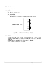
(2) Test connector
Connect the test connector shown in Figure B-3-6 to the interface connector
Figure B-3-6 Test Connector Connection Diagram
2.3.1.2 Function
After the settings outlined in Section 3.3.1.1 are completed and power is turned on, the serial
interface checks the message buffer memory and interface driver/receiver circuit. It then prints
characters.
To start and stop this test, push the SEL switch on the front of the printer.
Details of this test are explained on the next page.
Equivalent to Cannon DB-25P
TD
RD
RTS
CTS
CD
SSD
DTR
DSR
2
3
4
5
8
11
20
6
Summary of Contents for PACEMARK 4410
Page 2: ...1 PACEMARK 4410 PRINTER Service Manual...
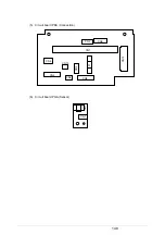
Page 53: ...52 Figure 3 1 3 2 Parts Layout...
Page 96: ...95...
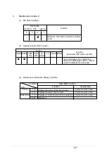
Page 152: ...151 No Yes End Replace PHA Board Recovered No Yes End Replace PMA Board...
Page 180: ...120 Knob Assy 40782001 8 4 6 3 5 10 7 1 2 9...
Page 182: ...122 Ribbon Assy Feed 40506101 1 15 8 7 8 14 6 5 10 13 3 4 13 2 6 7 14 9 11 11 1...
Page 184: ...124 Sprocket Assy L 40507601 3 2 5 6 1 19 19 7 4 21 10 8 9 20 18...
Page 186: ...126 Sprocket Assy R 40508101 3 7 11 11 1 6 5 2 13 4...
Page 190: ...130 Sheet Feeder Assy R Rear 40509101 8 11 1 9 4 13 13 10 6 5 2 9 12 7 3 Pin Protrusion...
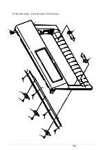
Page 196: ...136 Front Cover Assy 40677201 ODA 40677202 OEL 10 6 9 9 9 2 4 4 1 3 7 7 5 9 10 10 6 6...
Page 198: ...138 Rear Cover Assy 40678301 11 6 5 9 10 10 8 10 10 10 9 4 1 10 3 2 7 13...
Page 202: ...142 Frame Assy OpePane 40755801 3 2 4 6 8 9 9 1 5...
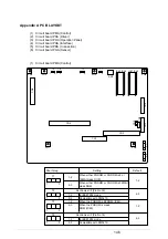
Page 204: ...144 PMA PDA PCB Assy 40752201 4075202 4 or 6 5 or 7 1 or 2 3 8 9 11...