OKIFAX º5700/5900
5 - 1
5.1
Setting of LED Print Head Drive Time
• Adjustment point: Technical Function: Setup No. 26
* To bring the LCD up to Technical Function, press MENU key once, RESOLUTION key
twice (In case of no message in memory).
Note:
When the rank marking of the replaced LED print head (new part) is the same
as that of the used LED print head (old part), you do not always have to set the
LED print head drive time.
Adjustment:
1) Turn AC power ON.
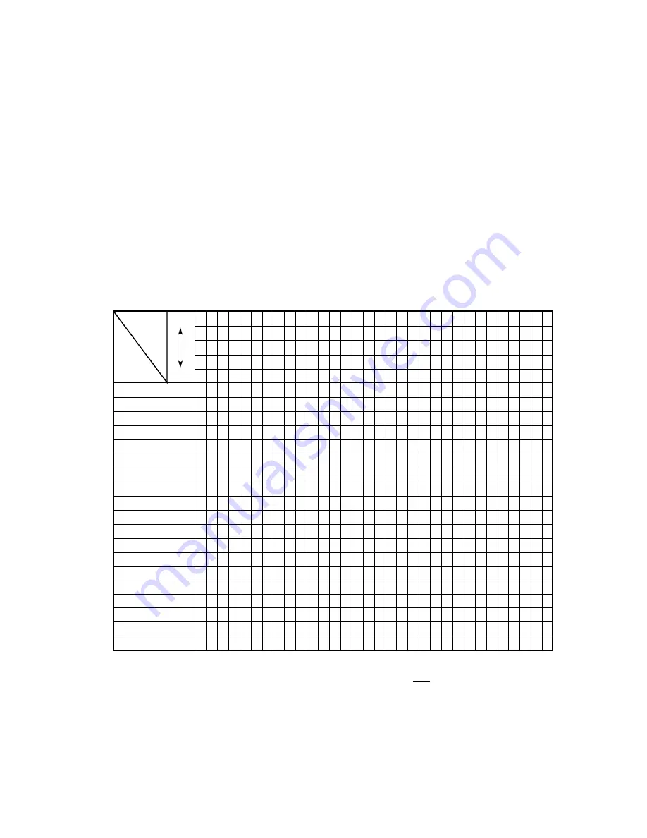
2) Setting of LED print head should be according to the Table 5.1.1 below:
Rank
Marking
Setting
MSB
LSB
0
0
0
0
0
0
0
0
0
1
0
0
0
1
0
0
0
0
1
1
0
0
1
0
0
0
0
1
0
1
0
0
1
1
0
0
0
1
1
1
0
1
0
0
0
0
1
0
0
1
0
1
0
1
0
0
1
0
1
1
0
1
1
0
0
0
1
1
0
1
0
1
1
1
0
0
1
1
1
1
1
1
1
1
1
1
1
1
1
0
1
1
1
0
1
1
1
1
0
0
1
1
0
1
1
1
1
0
1
0
1
1
0
0
1
1
1
0
0
0
1
0
1
1
1
1
0
1
1
0
1
0
1
0
1
1
0
1
0
0
1
0
0
1
1
1
0
0
1
0
1
0
0
0
1
1
0
0
0
0
085 –
080 – 084
074 – 079
070 – 073
065 – 069
061 – 064
058 – 060
053 – 057
050 – 052
047 – 049
044 – 046
041 – 043
038 – 040
036 – 037
033 – 035
031 – 032
029 – 030
027 – 028
– 026
*
*
*
*
*
*
*
*
*
*
*
*
*
*
*
*
*
*
*
Table 5.1.1 Setting of Technical Function: Set up No. 26
Note1: The luminous intensity ranking is determined by the first, second and third digits
from the right in the LED print head (i.e. in ---XX061, 061 is the luminous inten-
sity ranking.)
Note2: When the head label of the replaced LED print head (new part) is the same as
that of the used LED print head (old part), you do not always have to set the
LED print head width by technical function: Set up No.26. (Refer to table
2.9.2.3, TF No.26)
Summary of Contents for OKIFAX 5700
Page 6: ...CHAPTER 1 GENERAL INFORMATION ...
Page 90: ...CHAPTER 2 INSTALLATION PROCEDURE ...
Page 102: ...OKIFAX 5700 5900 2 12 3 Document stacker Hang the document stacker onto hanging position ...
Page 204: ...OKIFAX 5700 5900 2 114 Typical Transmission flow ...
Page 205: ...OKIFAX 5700 5900 2 115 Typical Reception flow ...
Page 210: ...CHAPTER 3 BRIEF TECHNICAL DESCRIPTION ...
Page 218: ...CHAPTER 4 MECHANICAL DISASSEMBLY AND REASSEMBLY ...
Page 223: ...OKIFAX 5700 5900 4 5 Appearance of the OKIFAX 5700 5900 ...
Page 248: ...CHAPTER 5 ADJUSTMENTS ...
Page 252: ...CHAPTER 6 CLEANING AND MAINTENANCE ...
Page 278: ...CHAPTER 7 TROUBLESHOOTING AND REPAIR FOR OKIFAX 5700 5900 ...
Page 390: ...C34 OKIFAX 5700 5900 A3 40 IC201 Pin Assignment ...
Page 405: ...Appendix B DescriptionsofPrintOperation ThirdEdition December 1998 Oki Data Corporation ...
Page 427: ...Appendix C Not used at this time ...
Page 430: ...OKIFAX 5700 5900 D 1 Section 1 CABINET ASSEMBLY ...
Page 432: ...OKIFAX 5700 5900 D 3 Section 2 CONTROL PANEL ASSEMBLY ...
Page 434: ...OKIFAX 5700 5900 D 5 Section 3 PRINTER ASSEMBLY 53 54 ...
Page 437: ...OKIFAX 5700 5900 D 8 Section 4 BASE ASSEMBLY ...
Page 439: ...OKIFAX 5700 5900 D 10 Section 5 FRAME ASSEMBLY SCANNER L ...
Page 441: ...OKIFAX 5700 5900 D 12 Section 6 FRAME ASSEMBLY SCANNER U ...
Page 443: ...OKIFAX 5700 5900 D 14 Section 7 CABLES OPTION BOARDS ...
Page 445: ...Appendix E Not used at this time Oki Data Corporation ...
Page 446: ...Appendix F Not used at this time Oki Data Corporation ...
Page 447: ...Appendix G PC Loading FirstEdition February 1999 Oki Data Corporation ...
Page 465: ...Appendix H RMCS SYSTEM MANUAL For Model 30 FirstEdition Oki Data Corporation ...
Page 466: ......


