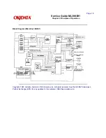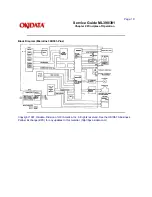
Q5 (128 kbytes) is the CGROM.
Electrically Erasable and Programmable Read Only Memory (EEPROM)
Menu data is stored in Q9 (256 bit), the EEPROM.
Large Scale Integrated Circuitry (LSI)
Q6 - MSM6990
This is an external interface and motor control LSI. It performs the following functions.
External Interface Controller
Parallel Interface Control
This circuit supplies signals used by the Centronics parallel interface.
Serial Interface Control
This circuit supplies signals used by the RS 232-C serial interface.
I/O Ports
Control signals are sent in response to commands input from the microprocessor. The input port is used to
read information on the printers condition.
Address Latch
It latches the low order eight bits of the address bus (A0 to A7). These bits are used as addresses for
read/write operations with peripheral devices.
Motor Controller
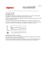
Spacing Motor Control
This function accelerates and decelerates the spacing motor in accordance with commands from the
microprocessor and controls the spacing motor speed in various printing modes. Motor speed and
direction are determined by monitoring the signals PHASE A and PHASE B, which are provided by the
encoder on the spacing motor.
DOT Timing Generation
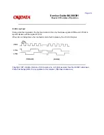
This function generates the DOT-ON signal (IPT), which synchronizes the print wire firing in accordance
with the signals PHASE A and PHASE B. This timing information is also sent to the microprocessor.
Q6 - MSM79H048, MSM79H097
This LSI controls the functions listed below.
Direct Memory Access (DMA) Control
Transfers data between the ROM and RAM or between RAMs independent of the microprocessor.
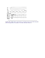
Printhead Drive Control
Drive pulses are produced for printwire drive timing using the signal IPT as a trigger. IPT is generated
from the signals PHASE A and PHASE B (which are produced by the spacing motor). The pulse width
(drive time) of IPT varies with the number of printwires to be fired. The duration of IPT is preset by the
microprocessor.
Print Data Transfer Control
Controls the serial transfer of print data. Print data is transferred from the print buffer to a register in this
LSI in synchronization with the IPT signal (provided by the MSM6990 LSI). The data stored in this register
will be transferred serially to the head drive circuits.
Summary of Contents for MICROLINE Turbo ML390
Page 49: ...Partner Exchange BPX for any updates to this material http bpx okidata com ...
Page 53: ...Page 29 Service Guide ML390 391 Chapter 2 Principles of Operation ...
Page 81: ......
Page 95: ...Partner Exchange BPX for any updates to this material http bpx okidata com ...
Page 106: ...Partner Exchange BPX for any updates to this material http bpx okidata com ...
Page 110: ......
Page 115: ......
Page 132: ......
Page 222: ......

