Oki C5650 Maintenance Instructions Manual Download Page 65

43827101TH  Rev.2

65 /

Oki  Data  CONFIDENTIAL

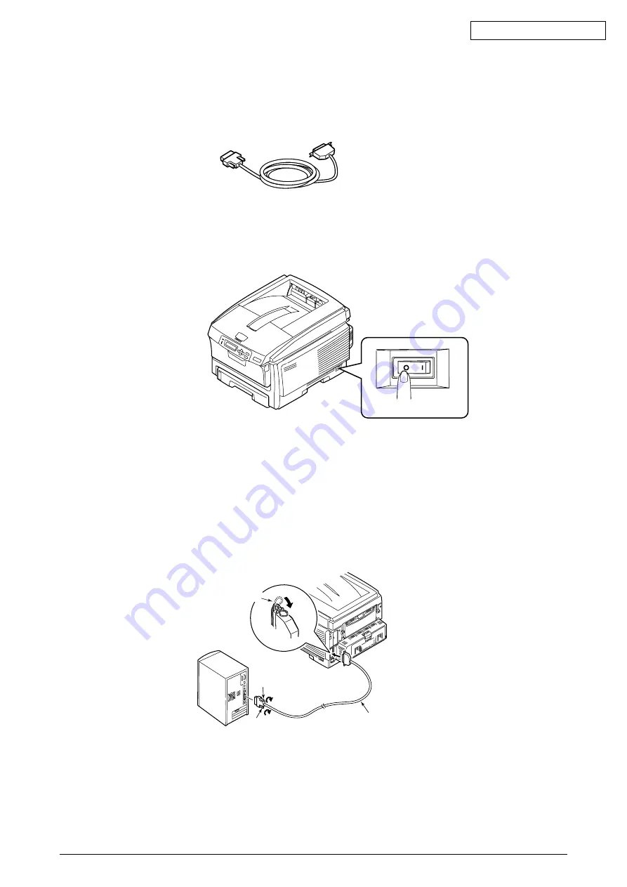
<Parallel Connection> (Centronics I/F model)

     1. Prepare a parallel cable.

     2. Power off Printer and Personal Computer

     3. Connect Personal Computer and Printer

(1)

Connect a parallel cable into a parallel interface connector of printer and use metal fittings to
secure the cable.

(2)

Connect a parallel cable into a parallel interface connector of PC and use screw to secure the
cable.

O

I

OFF

Parallel cable

Screw

Screw

Metal fittings

Summary of Contents for C5650

Page 1: ...Oki Data CONFIDENTIAL C5650 C6050 C6150 MPS6150c Maintenance Manual 080409B...

Page 2: ...acturers and referred to in this guide will not affect the applicability of the information in it Mention of software products manufactured by other companies does not necessarily constitute endorseme...

Page 3: ...at exhaustive efforts were made in preparing the manual to make it accurate it still may contain errors Oki Data will not hold itself liable for any damage that results or is claimed to have resulted...

Page 4: ...650 C6050 C6150 21 1 5 3 1 Outline of network interface 21 1 5 3 2 Network interface connectors and cables 22 1 5 3 3 Network interface signals 22 2 EXPLANATION OF OPERATION 23 2 1 Electrophotographic...

Page 5: ...Sensor 92 4 2 20 Fuser Unit 93 4 2 21 Belt Unit 94 4 3 Lubricating points 95 5 MAINTENANCE MENUS 113 5 1 System maintenance menu For maintenance personnel 113 5 2 Maintenance utility 116 5 3 Functions...

Page 6: ...en taking action on abnormal images 166 7 4 Preparations for troubleshooting 166 7 5 Troubleshooting method 166 7 5 1 LCD Message List 167 7 5 2 Preparing for troubleshooting 183 7 5 2 1 LCD Display M...

Page 7: ...7 5 3 6 Color registration is wide 228 7 5 3 7 Solid Black Print 229 7 5 4 Actions after forced initialization of HDD Flash 230 7 5 5 Network Troubleshooting 231 7 6 Check of fuses 232 8 CONNECTION DI...

Page 8: ...Fuser Unit Inlet EXIT sensor Density sensor Color registration PCB right Belt unit fuse cut Fuser fuse cut UP LOW thermistor frame thermistor Belt unit fuse cut EXIT Color drift density thermistor si...

Page 9: ...RED CPU Belt unit PU PCB Junction PCB Fuser Unit Inlet EXIT sensor Density sensor Belt unit fuse cut Fuser fuse cut UP LOW thermistor frame thermistor Belt unit fuse cut EXIT Color drift density therm...

Page 10: ...C6050 C6150 printer is composed of the following sections Electrophotographic processing section Paper paths Control sections CU sect PU sect Operator panel Power supply sections High voltage sect low...

Page 11: ...ter is composed of the following sections Electrophotographic processing section Paper paths Control sections CU sect PU sect Operator panel Power supply sections High volatge sect low voltage sect Fi...

Page 12: ...ond tray C5650 C6050 C6150 2 Duplex Unit C5650 C6050 C6150 3 Expansion Memory C6050 C6150 256 MB 512 MB For long printing it is recommended to add an expansion memory Not compatible with the expansion...

Page 13: ...Econo mode Toner saving by reducing lightness CPU Core PowerPC405 PowerPC750CL I cache 16KB 32KB D cache 16KB 32KB Internal L2 256KB Clock 200MHz 500MHz Bus width 32bit 64bit RAM Resident 64 MB 256 M...

Page 14: ...h 3 pages job Approx 12 000 pages With 1 page job Approx 27 000 pages When printed continuously Drum counter automatically reset Transfer belt life 60 000 pages A4 size with 3 pages job counter automa...

Page 15: ...p Provided Paper size Not provided Stacker full Not provided Standard On PCB Hi Speed USB Ethernet Additional Function Not available Bidirectional parallel I F conforming to IEEE std1284 1994 Input ou...

Page 16: ...26 22ppm 32 22ppm Optional Item Detacchable RAM set 64 256 MB 256 512 MB Tray mechanism 2nd tray mechanism Cassette Legal universal 530 sheets Two sided print unit Available Othes Not applicable 2 5...

Page 17: ...td equivalent product Cable 36pConnector Male 57FE 30360 20N D8 DDK Ltd equivalent product Item Details Corresponding mode Comatible mode nibble mode ECP mode Compatible 8 Nibble 4 ECP 9 bit Data bit...

Page 18: ...fline Online SW for Online Switching Timing d nlnit Timing Default Invalid PARALLEL DATA DATA BITs 1 to 8 nStrobe nAck BUSY 0 5 s min 0 5 s min 0 5 s min 0 5 s max 0 5 s min 0 min 0 min 0 5 s to 3 s 0...

Page 19: ...DATA 3 DATA 4 DATA 5 DATA 6 DATA 7 DATA 8 nAck PtrClk Busy PtrBusy PError AckDataReq Select Xflag nAutoFd HostBusy Unused GND FG 5V GND nInit nInit nFault nDataAvail GND Unused HILEVEL nSelectIn IEEE...

Page 20: ...ce connectors and cables 1 Connector Printer side B receptacle Female Upstream port Product equivalent to UBR24 4K5C00 Made by ACON 2 3 4 1 Connector pin assignment Cable side B plug Male 2 Cables Cab...

Page 21: ...interface C6050 C6150 Protocol family Network protocol Application TCP IP IPv4 TCP ICMP ARP UDP LPR RAW IPP FTP Telenet SNMPv1 DHCP BOOTP DNS UPnP Rendezvous SNTP Protocol family TCP IP NetBEUI NetWar...

Page 22: ...Connector pin assignment 2 Cables RJ 45 connectorized non shielded twisted pair cable Category 5 recommended 1 5 3 3 Network interface signals 1 8 Pin No Signal name Direction Function 1 2 3 4 5 6 7 8...

Page 23: ...arged toner adheres to the electrostatic latent image of the OPC drum by electrostatic power and forms a visible image on the OPC drum surface 4 Transfer Paper is placed over the OPC drum surface and...

Page 24: ...on the OPC drum surface 3 Development Toner adheres to the electrostatic latent image on the drum surface thereby turning the electrostatic latent image into a toner image 1 The sponge roller allows t...

Page 25: ...the transfer roller moves on to the surface of the paper through the contact part between the transfer roller and the paper the toner being attracted to the paper surface from the OPC drum surface Po...

Page 26: ...the waste toner box of the transfer belt unit Transport belt Belt waste toner box Belt cleaning blade 6 Removal of Electricity Electrically charge on the OPC drum surface decveases by exppsing the OP...

Page 27: ...sake of safety a thermostat is provided it comes on to cut off the voltage supplied to the heater if the heat roller temperature rises above a certain preset temperature Thermostat Thermistor Thermis...

Page 28: ...be explained below When two sided print is conducted the paper that has passed through the fuser unit following first one sided print is sucked into the Duplex unit by the separator DUP After entering...

Page 29: ...aper feed roller is driven 2 After causing the IN2 sensor to come ON the paper is further carried over a certain distance to finally hit register roller U This corrects skew of the paper 3 As shown in...

Page 30: ...ort roller placed immediately underneath each color drum with a transport belt inserted in between them Asthespecifiedvoltageisapplied thetransportbeltandthetransportrollerssendthepaper located on the...

Page 31: ...place driven by the lift up motor 2 Figure 2 6 shows the motions of the different ID units when the printer is operated for color print As the lift up motor rotates Clockwise turn the lift up link sl...

Page 32: ...aper Figure 2 8 Figure 2 9 6 Cover opening motion of color drift sensor and density sensor 1 As illustrated in Figure 2 9 when the fuser motor rotates Clockwise turn the cover opening gear rotates cau...

Page 33: ...rinted since previous execution A correction error may be issued due to an inadequate toner amount of the pattern generated a sensor stained with toner deficient opening closing of the shutter or for...

Page 34: ...ether the sensor shutter opens and closes normally by the MOTOR CLUTCH TEST of the self diagnostic function If the shutter operates imperfectly replace the shutter unit BELT REFLX ERR Check 4 If this...

Page 35: ...lose to those of a new product at power on When the ID count value exceeds 500 counts since previous execution A correction error may be issued due to an inadequate toner amount of the pattern generat...

Page 36: ...to the normal state Check 2 Check to see whether the sensor surface is stained with toner paper dust or any other foreign matter If it is found stained wipe it clean DENS SHUTTER ERR Check 3 Check to...

Page 37: ...e printer can print it is counted by an LSI as a number of print dots The amount of toner consumed is calculated from that count value and the remaining amount of toner is thus indicated As opposed to...

Page 38: ...e in any other manner than the way specified in the manual Failure to observe the above could result in fire Do not stick in an object into the vent hole Such action could lead to an electric shock fi...

Page 39: ...from a video monitor or TV To move the printer hold it by both sides of it This printer which weighs Approx 29kg with Duplex Approx 26kg w o Duplex should be lifted up by two or more persons When the...

Page 40: ...Make sure to lift up this printer by two or more persons since it weighs Approx 29kg with Duplex Approx 26kg w o Duplex Remove the four handles from the sides of the box as illustrated below and lift...

Page 41: ...t humidity 20 80 RH Relative humidity Max wet bulb temperature 25 C Use caution to avoid dew condensation If the printer is installed in a location with ambient relative humidity below 30 use a humidi...

Page 42: ...lift up this printer by two or more persons since it weighs Approx 29kg with Duplex Approx 26kg w o Duplex Personal injuries may occur Printer Main body Image drum cartridges 4 sets fitted with start...

Page 43: ...2 Draw out the paper cassette 3 Pull out the retainer forward 4 Open the top cover by pressing the OPEN button 5 Detach the stopper release Orange while pressing down the lever Blue of the fuser unit...

Page 44: ...the room lighting for over five minutes In the above operation be careful not to actuate the blue lever of the toner cartridge 2 Place the image drum cartridge on a flat top desk or the like peel off...

Page 45: ...cartridges supplied with the product can print approximately 1500 A4 size sheets with 5 print density If the error message REPLACE TONER stays permanently on the operator panel check to make sure that...

Page 46: ...nd line up its vertical and lateral edges 4 Load the paper with the print face down Note Place the paper aligned to the forward end of the paper cassette Load the paper by avoiding to exceed the mark...

Page 47: ...supporter 2 Set the manual feed guide to the paper size 3 Line up the vertical and lateral edges of the paper 4 Insert the paper print face up along the manual feed guide straight as far as it will g...

Page 48: ...er and put the Quick Guide in it Turning back the dedicated Quick Guide bag and peeling off the adhesive double coated tapes 2 Pasting the dedicated bag to the printer Note When pasting the bag avoid...

Page 49: ...g anything on the power cord Do not bundle or tie the power cord Do not use a damaged power cord Avoid a starburst connection of cables Do not connect the printer to the same power outlet shared by ot...

Page 50: ...to the ground terminal of the power outlet insert the power plug into the power outlet Pressing ON of the power switch The following indication will be produced on the operator panel and Online will a...

Page 51: ...do not outright turn off the power but follow the procedure described below Note Abrupt disconnection of the power could damage the built in hard type disk disabling it SHUTDOWN MENU is displayed only...

Page 52: ...n memories for C6050 C6150 and those for C5650 are not compatible with each other The expansion memories for C5850 are not compatible with those for C5200 series and C5800 C5600 C5500 Turning OFF the...

Page 53: ...bag place the bag in contact with a metal part to fuser eliminate its static electricity 2 Insert the memory into the idle slot 3 Ensure that it is securely fastened by the right and left lock levers...

Page 54: ...lock levers Note Do not touch the electronic parts and connector pins Pay attention to the orientation of the memory The terminal part of the memory has a notch which is designed to engage with the co...

Page 55: ...power and disconnecting the power cord Note If an expansion memory is installed with the power switched ON the printer may be broken Placing the printer on the second tray unit Note The printer weigh...

Page 56: ...ower and disconnecting the power cord Note If an expansion memory is installed with the power switched ON the printer may be broken Peeling the protective tapes off the duplex unit Install Duplex Unit...

Page 57: ...as a built in type hard disk installed make certain to switch off the printer after executing the shutdown menu If the power is turned off outright the hard disk may be damaged and broken Memo The har...

Page 58: ...by pressing the OPEN button 2 Push up the handle located in the center of the front cover and pull the front cover forward Note The way the front cover is opened is different from that of the multi p...

Page 59: ...hing the side cover check to see if the front cover is open Installing the built in type hard disk 1 Insert part a of the built in type hard disk into hole b of the printer main body and align the pos...

Page 60: ...Map print by referring to 3 6 Menu Map print 2 Ensure that the capacity of the built in type hard disk is indicated in HDD Memo The capacity of the hard disk may be different from the example shown ab...

Page 61: ...ory Checking the contents of the Menu Map Check the total memory volume indicated in Total Memory Size of the header 2 Confirmation of recognition of second tray Confirmation of recognition of second...

Page 62: ...enu tobedisplayed 3 Press the Set switch to cause PRINT MENU MAP EXECUTE to appear 4 Press the Set switch The Menu Map print will get under way Two pages on the C5950 and one on the C5850 When Network...

Page 63: ...43827101TH Rev 2 63 Oki Data CONFIDENTIAL...

Page 64: ...The USB cable can be plugged in or unplugged with the computer and printer switched ON However to be able to conduct the subsequent installation of the printer driver and USB driver securely the power...

Page 65: ...nd Personal Computer 3 Connect Personal Computer and Printer 1 Connect a parallel cable into a parallel interface connector of printer and use metal fittings to secure the cable 2 Connect a parallel c...

Page 66: ...ENTIAL Network interface connector LAN cable connection Preparing a LAN cable Switching off the printer and computer 1 Plug the Ethernet cable into the Network interface connector of the printer 2 Ins...

Page 67: ...at the printouts are free from toner flaking 1 The printer comes with Media Type set to Light at the factory 2 The thickness and type of paper can be set on the operator panel and also via the printer...

Page 68: ...d replacement procedures for parts assemblies and component units While those replacement procedures refer to the disassembling of parts follow the same procedures inversely for reassembling them The...

Page 69: ...nance utilities Table 4 1 2 Maintenance Tools No Q ty Place of use Remarks Service Tools 1 2 3 4 5 6 8 No 2 200 Philips screwdriver Magnetized No 3 100 screwdriver No 5 200 screwdriver Digital multime...

Page 70: ...explains the replacement methods for the parts and assemblies illustrated in the disassembly system diagram below 4 2 1 Left side cover 1 Open the top cover 2 Open the feeder unit 3 Remove screw silve...

Page 71: ...H Rev 2 71 Oki Data CONFIDENTIAL 4 2 2 Right side cover 1 Open the top cover 2 Open the feeder unit 3 Loosen screw 1 and detach right side cover 2 Figure 4 2 2 Right side cover 2 1 Feeder unit Top cov...

Page 72: ...2 72 Oki Data CONFIDENTIAL 4 2 3 Face Up Tray 1 Open face up tray 1 into the direction of the arrow free the engagement on either side of it while deflecting the tray and remove the tray Figure 4 2 3...

Page 73: ...n Figure 2 and release two claws A 4 Now release two claws B and pull the upper part of rear cover 2 in the direction of arrow A 5 Push the lower part of rear cover 2 in the direction of arrow B as sh...

Page 74: ...irst free hook part A by applying force in the direction of the arrow as illustrated in Figure 2 and then free hook part B to finally remove LED Assy 1 In this operation two springs2will come out toge...

Page 75: ...ion 4 2 2 3 Remove eight screws silver 1 and detach plate shield assembly PDL 2 by releasing connector claws A 4 Remove screw 3 and disconnect head cable 4 5 Remove seven screws silver 5 disconnect al...

Page 76: ...n 4 2 2 3 Remove eight screws silver 1 and detach plate shield Assy GDI 2 by releasing claws A 4 Remove screw silver 3 and disconnect head cable 4 5 Remove seven screws silver 5 disconnect all the cab...

Page 77: ...PCL GDI See Subsection 4 2 6 1 through 3 2 Remove all the connectors and two screws silver 1 and disassemble the print engine controller PCB 2 Figure 4 2 7 1 Print Engine Controller PCB DCHEAT RELAY P...

Page 78: ...l panel Controller PCB Fuser motor PE cable FSNS Front sensor cable Option DUP 2nd Paper feed solenoid Option 2ND cable Junction PCB High voltage power supply Low voltage power cable Belt ID UP motor...

Page 79: ...ee Subsection 4 2 2 3 Detach the rear cover See Subsection 4 2 4 4 Remove the plate assembly shield GDI and then the control PCB See Subsection 4 2 6 5 After unplugging the connector disconnect hooked...

Page 80: ...1TH Rev 2 80 Oki Data CONFIDENTIAL 4 2 9 Top cover 1 Detach the top cover assembly See Subsection 4 2 8 2 Remove ten screws black 1 and detach cable cover 2 and top cover 3 Figure 4 2 9 Top cover 1 1...

Page 81: ...it 3 Detach the right side cover See Subsection 4 2 3 4 Remove the plate shield assembly See Subsection 4 2 7 2 5 After unplugging the connector of the control panel assembly free the hook 6 Remove fo...

Page 82: ...frame OP1 lever lock 2 and spring compression 3 3 Release two claws B by forcing in the flat tipped screwdriver and remove the cover assembly OP4 and spring torsion 5 4 Release two claws C of the cove...

Page 83: ...0 unplug the connector and disassembleFuser Motor A 11 Remove three screws silver B unplug the connector and disassemble ID motor C Note When reassembling low voltage fan 6 confirm the direction When...

Page 84: ...thermistor remove two spring torsions 1 and disassemble cover driver 2 by freeing the four claws with the flat tipped screwdriver 4 Remove screws silver 3 and unplug the six connectors to disassemble...

Page 85: ...elt motor To print engine controller PCB Color registration sensor Heater AC Black white Heater thermistor F cut Black white PU I F connector Driver junction PCB Exit sensor Density sensor Fuser unit...

Page 86: ...4 Unplug the connector and remove Fan Fuser 4 by turning it clockwise 5 Free the connector and two claws A and remove cover open switch 5 6 Remove screws silver 6 and seven claws B unplug the two con...

Page 87: ...Assy 1 Open MPT Assy 1 2 Release the two stoppers by opening the two arms of MPT Assy 1 toward the outside pull the assembly in the direction of the arrow to free the two fulcrums and detach MPT Assy...

Page 88: ...ctor and disassemble Front sensor PCB 5 7 Remove MPT Assy See Subsection 4 2 15 8 Detach lever 6 by turning it until its claw is freed 9 Remove two screws black 7 and detach stay L 1 10 Remove four sc...

Page 89: ...Subsection 4 2 15 8 Remove gear 4 by releasing the two latches and remove gear 5 by releasing the latch Then remove shaft 7 by releasing the latch of gear 6 9 Remove two screws silver 8 and disassemb...

Page 90: ...as mark figure Lift up motor Install aligninig the two position cut as mark figure 1 2 9 8 8 B B A H D C D C M N K 6 4 G 6 E P O O U Q R Z 3 W V X T Y I I 4 5 5 G 6 E 1 L View A View A 4 G Fit positio...

Page 91: ...43827101TH Rev 2 91 Oki Data CONFIDENTIAL 4 2 18 Feed Roller 1 Remove the cassette 2 Release the latch and remove feed roller 1 Figure 4 2 18 Feed Roller 1 Latch...

Page 92: ...ion 4 2 13 2 Free the two claws and divide the Assy between guide into lower 1 and guide eject upper 2 3 Removegearidleeject3 anddisassembleshaftAssyeject FU 4andshaftAssyeject FD 5 and Gear eject 6 4...

Page 93: ...2 93 Oki Data CONFIDENTIAL 4 2 20 Fuser Unit 1 Open the top cover 2 Lift up the lock levers 1 2 blue of the fuser unit in the direction of the arrow and remove fuser unit 2 Figure4 2 20 Fuser Unit 2 1...

Page 94: ...Unit 1 Open the top cover 2 Remove ID unit 1 3 Turn the lock levers 2 blue of belt unit 2 in the direction of the arrow and hold belt unit 2 by the levers Blue to remove it Figure 4 2 21 Belt Unit 2 1...

Page 95: ...e lubricated Thereisnoneedtolubricateinthemidstofadisassemblingjob However iflubricatingoilhasbeen wiped off supply the specified oil Lubricating work 1 Symbols and names of oils EM 30L MOLYKOTE EM 30...

Page 96: ...Plate Gear HP Caulking Shaft Hopping End surfaces Gear bottom surface EM 30L Class C Side faces of shaft groove section EM 30L Class C Gear teeth and end surface EM 30L Class C Latch claws Hatched pa...

Page 97: ...9701 Guide Assy Cassette L 3 43294901 Guide Assy Cassette R EM 30L Class C Guide Casette L Apply a normal amount of Molycoat EM 30L to the hatched portions EM 30L Class C Guide Casette R Apply a norma...

Page 98: ...CONFIDENTIAL 5 43072101 Gear Planet Assy Class B Spring Planet Heat Holder Gear A EM 30L Class C Apply a normal amount of Molycoat EM 30L to the hatched areas Apply a amount of HP 300 to the hatched a...

Page 99: ...OTE EM 30L in a large quantity to the gear tooth flanks at over 120 deg Enlarged view EM 30L Class F Gear Idle DrumZ24 102 Gear LiftUp Z21Z34 Gear LiftUp Z21Z34 Gear Idle Z44 EM 30L Class C EM 30L Cla...

Page 100: ...NTIAL EM 30L Class F Gear Idle Heat_Z14 Z32 Gear Planet Assy Motor DC FC 45M Grease prohibition to post Grease prohibition to gear Apply a large around of MOLYKOTE EM 30L to all gear teeth Gear Idle E...

Page 101: ...56 Plate Side R Caulking Apply MOLYKOTE EM 30L in a small quantity to the hatched parts Apply MOLYKOTE EM 30L in a normal quantity to the gear tooth tip Apply MOLYKOTE EM 30L in a small quantity to th...

Page 102: ...30L Class A EM 30L Class A EM 30L Class C Apply MOLYKOTE EM 30L in a normal quantity to the gear tooth tips Apply MOLYKOTE EM 30L in a small quantity to the hatched part Apply MOLYKOTE EM 30L in a sm...

Page 103: ...er Assy Regist L Holder Regist L EM 30L Class C Apply MOLYKOTE EM 30L in a normal quantity to the hatched parts parts having the rotation shafts inserted Holder Regist R EM 30L Class C Apply MOLYKOTE...

Page 104: ...t apply grease to the boss Do not apply grease to the gears Assemble after applying MOLYKOTE EM 30L to the hatched parts in the illustration below both right and left Fulcrums of rotation and side par...

Page 105: ...points Grease must not stick to the paper paths Apply MOLYKOTE EM 30L in a normal quantity to the bearings 2 points Apply MOLYKOTE EM 30L in a normal quantity to the post surfaces parts having the sha...

Page 106: ...Assy Base Cassette Assy PM Class C Apply PM in a small quantity to the hatched part 1 Applying method Wipe the part with a cloth slightly impregnated with PM 2 After applying PM insert and pull out th...

Page 107: ...EM 30L Class C EM 30L Class C EM 30L Class C Apply MOLYKOTE EM 30L in a normal quantity to the tips of the terminals 4 points Applied range of grease 4 points Apply MOLYKOTE EM 30L in a normal quantit...

Page 108: ...01 Printer Unit Plate Ass Side R Spring Torsion L EM 30L Class C 2 places At both Sides Spring Torsion R Apply MOLYKOTE EM 30L in a normal quantity to the hatched parts Apply PM to the slot parts of t...

Page 109: ...Bearing TR Belt 4 points Apply MOLYKOTE EM 30L in a normal quantity to the bearings both sides Enlarged view Enlarged view Apply MOLYKOTE EM 30L in a normal quantity to the bearings both sides Apply M...

Page 110: ...Sensor Assy Color Regist Plate Sensor C Regist Cover Sensor C Regist Shaft Cover Sensor EM 30L Class A Apply MOLYKOTE EM 30L in a small quantity to the hatched parts At both Sides 8 points MOLYKOTE mu...

Page 111: ...G 43081301 Roller Assy Idle FD 1 2 Grease applying method Before assembling 2 to 1 apply MOLYKOTE EM 30L in a very small quantity Class S to the sliding parts hatched parts between 1 and 2 Disassemble...

Page 112: ...ONFIDENTIAL H 43301601 Roller Assy BIAS FU C 1 2 3 Grease applying method Range in which grease must not stick Before assembling 3 to 2 apply MOLYKOTE EM 30L in a very small quantity Class S to the sl...

Page 113: ...h ROM When this item is executed the menu is dismissed and formatting of the flash device mounted in the Resident Onboard begins CAUTION NIC F W will be erased see section 7 5 4 Resets the EEPROM cont...

Page 114: ...be displayed at all When the menu is dismissed after changing the setting the printer is restarted Setting is made here to select either to display or not to display USER MENU USAGE MENU TOTAL PAGE C...

Page 115: ...development If IBM PPR III XL and EPSON FX are set to ENABLE on a printer for domestic market its operation is not guaranteed Activates the self diagnostic mode of the engine Function Item 1st Line Va...

Page 116: ...FU01 Rev5 or later Japanese 42678801FU02 Rev5 or later English 2 The maintenance utility programs are indicated below The programs can be downloaded from the FTP server for manuals Window Person in ch...

Page 117: ...to another PU PCB in the event that the current PU PCB needs to be replaced due to maintenance replacement Reprogramming printer serial number recorded on PU Adjustment Purpose Set for a board replace...

Page 118: ...ect 2 4 2 2 7 3 Section 2 4 1 2 6 Section 2 4 1 3 1 Section 2 4 1 3 2 Section 2 4 1 2 6 Section 2 4 1 3 1 Section 2 4 1 3 2 Section 2 4 1 3 3 Section 2 4 1 3 4 Section 2 4 1 4 1 Subsect 2 4 1 5 1 Subs...

Page 119: ...nter indication Local parameter setup Engine parameter setting Prohibited to use Subsect 2 4 1 5 7 Subsect 2 4 1 5 8 Subsect 2 4 1 5 9 Setup of automatic density setting control parameters Verificatio...

Page 120: ...With scattering or snowing images in print output of high print density decrement the value With faded images in print output of high print density increment the value Used to correct dispersion of p...

Page 121: ...in print results caused by temperature humility conditions and difference in print density frequency Change the setting when background is dark Maintenance Menu BG SETTING 3 2 1 0 1 2 3 Function Categ...

Page 122: ...intenance menu is displayed Then select ENGINE DIAG MODE and press ENTER Not pressed LEVEL0 engine status indication LEVEL1 ENGINE DIAG MODE XX XX Engine status indication SWITCH SCAN Heater temperatu...

Page 123: ...er sensor status monitoring indication MENU Error code indication etc Charge CH voltage Supply SB voltage Development DB voltage Environmental level Registration motor speed setting Fuser motor speed...

Page 124: ...Y 04 CRSE ADJ C X DELTA Y 07 FINE ADJ Y Y L DELTA M 01 FINE ADJ Y Y L DELTA M 04 FINE ADJ Y Y R DELTA M 07 FINE ADJ Y Y R DELTA C 01 FINE ADJ Y X L DELTA C 04 FINE ADJ Y X R DELTA C 07 FINE ADJ M Y L...

Page 125: ...part continuance counter Factory Shipping mode switching Check of Fuse status Engine parameter setup Indication of LED head serial number SWITCH SCAN MOTOR CLTCH TEST TEST PRINT REG ADJUST TEST DENS...

Page 126: ...is self diagnosis is practiced to check the inlet sensors and switches 1 Activate the self diagnostic mode Level 1 press and hold down the MENU or MENU key until SWITCH SCAN appears in the upper line...

Page 127: ...or Upper compensation Exit sensor Duplex print inlet sensor Duplex print bottom sensor Duplex print cover open sensor Duplex print front sensor 1st tray sensor ID Up Down sensor Fuser unit thermistor...

Page 128: ...ue H Aligment Right Sns AD value H 5 HT THERMISTER Upper Center Thermister AD value H Lower Center Thermister AD value H Ambient Temp Thermister Frame Temp AD value H 6 HUM_TEMP_DEN Hum Sns AD value H...

Page 129: ...inking and the corresponding unit is driven for ten seconds See Figure 5 2 Note After the unit has been driven for ten seconds the status of Item 2 above is restored The unit is driven again when the...

Page 130: ...he IDs Black yellow magenta cyan removed To be driven with all the IDs Black yellow magenta cyan removed Tray 1 hopping motor only is driven To be driven with Cassette 1 removed Hopping solenoid drive...

Page 131: ...lower line Pressing the MENU key increments the set value and pressing the MENU key decrements it the set value finally displayed will be applied Pressing the BACK key defines the value and restores...

Page 132: ...Pattern 1 Pattern 2 Notes PAGE setup After shifting the digit of the set value with the MENU key or MENU key press the ONLINE key The set value will be incremented Pressing the CANCEL key decrements i...

Page 133: ...available among the local print functions is conducted with 100 of each color offset will take place To prevent this offset it will be necessary to make the print setup of each color as specified in 3...

Page 134: ...ity Unit Pressing the MENU key switches over the indication YTR MTR CTR and KTR denote the transfer voltage set values of the respective colors Unit KV Pressing the MENU key switches over the indicati...

Page 135: ...parameter VTR1 table ID No Unit HEX TR2 Transfer voltage parameter VTR2 table ID No Unit HEX Pressing the MENU key switches over the indication TROFF BELT xxx TROFF Transfer OFF voltage setup table I...

Page 136: ...display section and RESULT in the lower line Pressing the MENU key increments the test result sequentially in the display Pressing the MENU key decrements the test result sequentially in the display...

Page 137: ...wing message to appear Press and hold down the MENU key or MENU key until the intended item is displayed 3 Pressing the ENTER key executes the test of the item currently displayed on the panel DENS AD...

Page 138: ...ts the test result sequentially in the display Pressing the MENU key decrements the test result sequentially in the display Pressing the BACK key restores the status of Item 2 3 Pressing the CANCEL ke...

Page 139: ...LL M TONER FULL C TONER FULL M WASTE TNR CNT C WASTE TNR CNT K STC MODE CNT Y STC MODE CNT M STC MODE CNT C STC MODE CNT K REFILL CNT Y REFILL CNT M REFILL CNT C REFILL CNT K OVER RIDE CNT Y OVER RIDE...

Page 140: ...Shipping mode 1 Activate the self diagnostic Level 1 mode and press and hold down the MENU key or MENU key until the following message appears 2 Pressing the ENTER key causes the following message to...

Page 141: ...select the set value in the lower line of the display section Pressing the MENU key increments the set value Pressing the MENU key decrements the set value 4 Pressing and holding down 3 sec the ENTER...

Page 142: ...BLE DISABLE STOP CONTINUANCE Hatched part Denotes the default 5 3 2 12 Indication of LED head serial number This self diagnosis is practiced to check whether a downloaded LED head data matches the ser...

Page 143: ...f a system maintenance menu is performed The function mentioned above is secret to users Therefore this status does not occur in a user environment Displays that Flash memory is being formatted It is...

Page 144: ...that an error takes place while a program data to update is being received DLCODE 1 Size Error 2 Check SUM Error 3 Printer Model No Error 4 Module I F Version Error 5 FAT Version Error Displays that...

Page 145: ...rned on pressing a Enter Back Down switch it will enter into this mode This function is secret to users Therefore this status does not occur in a user environment Shows on line status Shows off line s...

Page 146: ...job being cancelled due to no print permit Related to JobAccount 1 A job received from a user who is denied printing 2 A color job received from a user who is denied color printing Indicates that a j...

Page 147: ...it is set to Toner Empty Arbitrary errors are errors of Priority 301 361 TONER LOW status occurs when the power is on the LED of ATTENTION in a case of LOWER TONER STOP is blinked and go back to the o...

Page 148: ...printer stops at the point when it reaches the drum life Shifts to error OFF LINE Moreover when set as NearLifeLED Disable Attention LED is switched off Y M C K Notifies the fuser unit is near its li...

Page 149: ...atus does not occur in a user environment Density Adjustment Shutter Error 2 Error that does not occur at user level Displayed only in FactoryMode PU firmware does not notify this warning to CU firmwa...

Page 150: ...ation error This error does not occur in the user s environment because the PU firmware does not notify the CU firmware of this status detected in Shipping Mode Density Adjustment ID ERROR 2 smear due...

Page 151: ...ipping Mode Therefore this status does not occur in a user environment Y M C K TRAY The tray is empty Treated as Warning until printing to the empty tray is designated Tray1 Tray2 Disk full is occurri...

Page 152: ...icates that an applicable job has been automatically deleted as the retention period for authentication printing has expired C6150 C6050 A disk error is occurred which is other than the file system fi...

Page 153: ...aper feed is required Manually insert the paper shown by MEDIA_SIZE The unit of paper size in Custom The unit specified for MPTray menu setting is used if no unit is specified by the driver When the d...

Page 154: ...TER key 5 3 4 Functions of keys when depressed at power on The different keys provide the following functions when the power is turned on to the printer The following keys turn effective when pressed...

Page 155: ...tice that if the printer has an error currently issued the error is also displayed in the Forced ONLINE mode 1 When turning on the printer press and hold down the BACK MENU ENTER keys until STATUS MOD...

Page 156: ...tination the PU Serial Number is output as a Lot Number in the Lot Number field in the bottom line of the Menu Map header section after the configuration at the UK Plant See 1 2 of Subsection 5 4 2 2...

Page 157: ...ber count Toner Yellow toner amounts used Toner Magenta Toner Cyan Total number of Printer life count Total number of sheets fed sheets fed Pages Black Respective numbers Numbers of pages impressed im...

Page 158: ...erial number setting is unnecessary 2 For OEL destination For CU Serial Number a unique Serial Number within 12 digits is assigned at the UK Plant Notice that when the CU Serial Number is set the menu...

Page 159: ...the default setting is OEL Note This setting is stored on the EEPROM of the CU PCB 1 Setup on the operation panel Start the printer in the maintenance mode and set the destination Turn on the power wi...

Page 160: ...ity setting may be displaced with the use along the time Execute this manual setup when the density appears below par Note Make the setup when the printer remains at a standstill Do not conduct it dur...

Page 161: ...refulnottotouchtheimagedrumterminals LEDlensarrayandLEDheadconnectors 6 3 Cleaning of LED lens array If a vertical white band or white stripe partial print light print is observed in the print face cl...

Page 162: ...essing the OPEN button The fuser unit is extremely hot Do not touch it Personal injuries may occur OPEN button 3 Wipe lightly the four lens surfaces of the LED head with the LED lens cleaner or a soft...

Page 163: ...d rollers large and feed rollers small using a piece of cloth impregnated with water and squeezed hard or the LED lens cleaner Note An LED lens cleaner is enclosed in an optional replacement toner car...

Page 164: ...he OPEN button The fuser unit is extremely hot Do not touch it Personal injuries may occur OPEN button 3 Take out the image drum cartridges 1 Take out the four image drum cartridges and place them on...

Page 165: ...the fuser unit lock levers 2 blue in the direction of the arrow 2 Take out the fuser unit holding it by the handle Fuser unit locking lever blue Handle Fuser unit locking lever blue 5 Wipe the metal s...

Page 166: ...recautions when taking action on abnormal images 1 Do not bring your hand or any object in contact with the surface of the OPC drum 2 Do not expose the OPC drum to direct sun 3 Do not touch the fuser...

Page 167: ...ter you have closed the tray and the lever lifted tttttt TrayName mmmmmm PaperName pppppp MediaTypeName Error 661 Tray1 Error 662 Ttay2 Error 461 Tray1 Error 462 Ttay2 Paper size displays in Custom mo...

Page 168: ...es not match the print data Load paper in tray It takes a while until the status disappears after you have closed the tray and the lever lifted Error 460 MPTray The paper size displaying form of the c...

Page 169: ...note When the ONLINE button was pressed the controller CU should send MPTPECLR command to the engine PU The engine would clear this state after receiving that command This error is occurred when the M...

Page 170: ...ame operation as job reset C6150 C6050 Density of the destination image for woven pattern is greater than that of the woven pattern A user must take measures such as increasing density of the woven pa...

Page 171: ...n Close 3 With no automatic concentration compensation 4 This error is displayed and it stops The signature ID of toner cartridge is not proper to the distribution channel and the group of signature I...

Page 172: ...played and it stops Something is wrong with the toner sensor This status is indicated in Shipping Mode only If the same error is detected in FACTORY Mode it is indicated as service call of 163 Error 5...

Page 173: ...user exchanges the image drum Notifies the fuser has reached its life This is the error displayed based on the counter to indicate that the fuser has reached its life and printing will stop Warning s...

Page 174: ...r is receiving the download data The printer finished receiving the download data An error has happened while the printer is receive processing the download data DLCODE 1 File size error 2 Check sum e...

Page 175: ...er completed shutdown processing The backlight of LCD puts out the light Printer will be restarted if a SHUTDOWN RESTART button is pressed A dew is formed Fatal Error is not available in national lang...

Page 176: ...pear Does error display reappear MachineCheck Exception Hardwarefault detected Board defectivenessor Shortageofpower supplyvolume CPU Exception CU ROM Hash Check Error CU Font ROM Hash Check Error CU...

Page 177: ...ith the Maintenance Utility after the initialization Execute FLASH FORMAT of MAINTENANCEMENUof theSystemMaintenance Menu When FLASH FORMAT is displayed releasethekeyandwaittill ONLINE approx 2min Ifth...

Page 178: ...ex Unit of C5400 C5200 Install 2nd Tray of C5400 C5200 Replace the FAN motor Replace the PU PCB Replace the PU PCB Connect properly Check improper connec tions for high voltage Replace high voltage po...

Page 179: ...d PU PCB replaceToner sensor PCB Replace PU PCB Reset belt unit Turn power ON again Check cable connec tions and replace PU PCB After cleaning for fuser connector reset Turn power ON again Check cable...

Page 180: ...ower ON again Replace fuser unit Turn power ON again After checking connection parts of connector replace option unit Turn power ON again Add option RAM DIMM Turn the printer OFF ON and retry to downl...

Page 181: ...cation be reproduced Is belt thermistor cable setting proper Does error reoccur Reset original HDD Check the connection of the RFID R W board Replace the RFID R W board Replace the PU PCB 01 Same as E...

Page 182: ...on again The black image drum K ID does not rotate properly Is the error message issued again when the power is turned on The fuser unit does not rotate properly Does the error reoccur after power cy...

Page 183: ...ccurs right after reaching the fuser unit 204 6 Paper Exit Jam Error 382 205 6 1 Paper exit jam occurs right after turning on the power 205 6 2 Paper exit jam occurs right after feeding paper 206 6 3...

Page 184: ...e control PCB 14 LED head is not recognized Error 131 132 133 134 216 14 1 Service Call 131 134 LED HEAD Missing 216 15 Toner cartridge is not recognized Error 540 541 542 543 217 15 1 Errors caused b...

Page 185: ...skew insertion Check for wire breakage with a circuit tester Also check visually for peel off of the covering Check to see if the 12pin FFC is properly plugged into the CUIF connector of the PU PCB Ch...

Page 186: ...h as dislocated wire etc Check to see if the wires are properly connected on a 1 pin to 1 pin basis Check to see if the 7 pin FFC is properly plugged into the OPE connector of the PU PCB Check to see...

Page 187: ...RAM DIMM HDD a genuine part This indication will be produced following upgrading of the PU firmware version Verify the PU version by conducting Menu Print or using the maintenance function Action at...

Page 188: ...e setting of low voltage power supply unit 100 V system 230 V system 5V and 24V power supplied to the PU PCB Connected state of operator panel 2 1 1 Check of parts related to power supply 2 1 2 Check...

Page 189: ...ck in the presence and absence of a load If abnormal the motors will emit pup pup Visually check to see if the consumables are installed in the prescribed positions where their gears are engaged Check...

Page 190: ...G Conduct 2 3 2 Replace the low voltage power supply unit If the unit is like new it necessarily emits some foul smell Remove the foreign matter 2 3 1 Location of source of foul smell 2 3 2 Check of s...

Page 191: ...372 373 380 381 382 383 385 390 391 392 400 Name Duplex reversal Duplex input Feed error at Duplex Multi feed in Duplex Unit Feed Transport Exit Duplex entry Around Fuser Unit Feed error at front feed...

Page 192: ...lly If that is the case opening and closing of the cover will clear the error If you see the rear edge of paper Front cover Paper If you see the top edge of paper Front cover Paper If you do not see t...

Page 193: ...remove the paper Possible to get burned 1 Raise the lock levers 2 blue of the fuser unit in the direction of the arrows 2 Take out the fuser unit holding it by the handle and place it on a flat table...

Page 194: ...as been removed from the fuser unit section unfixed toner may still remain inside the fuser unit Therefore execute the Menu Map print Subsection 3 6 or print blank paper several times If the paper jam...

Page 195: ...parts are extremely vulnerable Use good caution in handling them Do not expose the image drum cartridges to direct sun or intense light over approximately 1500 luxes Even under the room lighting do no...

Page 196: ...e jammed paper into the direction of the arrow and then pull it out slowly Fuser unit Paper WHEN THE TRAILING END OF THE PAPER IS VISIBLE While pushing the lever of the fuser unit into the direction o...

Page 197: ...r is not visible close the two sided print unit cover briefly and the paper will be unloaded automatically Note If the two sided print unit needs to be drawn out turn off the power of the printer Dupl...

Page 198: ...onfirm that the above signal levels vary as the sensor levers are actuated Check the 5 V power through the CN connector of the front sensor PCB Pin 5 5V power Pin 1 0VL Action at NG Remove the jammed...

Page 199: ...hether there is an approximately 3 4 or 5 resistance between pins 1 and 2 and pins 3 and 4 Conduct the Motor and Clutch Test of the self diagnostic mode and check to see if the feed solenoid operates...

Page 200: ...ormal shape or motion Use the SWITCH SCAN function of the self diagnostic mode to check to see if the sensor signal is detected normally Check the following signals through the FSNS connector of the P...

Page 201: ...llowing on the connector side Several Mohms between pin 1 and FG Several Mohms between pin 2 and FG Several Mohms between pin 3 and FG Several Mohms between pin 4 and FG Check a connection status of t...

Page 202: ...the operation Use the SWITCH SCAN function of the self diagnostic mode to check to see if the sensor signal is detected normally Check the following signal through the FSNS connector of the PU PCB Pin...

Page 203: ...al Mohms between pin 3 and FG Several Mohms between pin 4 and FG Unplug the BELTIDUP connector of the PU PCB and confirm the following on the connector side Several Mohms between pin 1 and FG Several...

Page 204: ...pin 3 and FG Short circuiting between pin 4 and FG Unplug the BELTIDUP connector of the PU PCB and confirm the following on the cord side Short circuiting between pin 1 and FG Short circuiting betwee...

Page 205: ...ral M between pin 4 and FG Unplug the BELTIDUP connector of the PU PCB and confirm the following on the connector side Several M between pin 1 and FG Several M between pin 2 and FG Several M between p...

Page 206: ...ormally low or high temperature is detected Check to see if the fuser unit is properly installed whether it is pushed in to the lowest position Action at NG Replace the PU PCB Replace the fuser motor...

Page 207: ...tor of the PU PCB Pin 9 EXIT sensor Confirm that the signal level varies as the sensor lever is actuated Check the 5 V power through the EXIT connector of the junction PCB Pin 1 5 V power Pin 3 0 VL C...

Page 208: ...te of the delivery section Check to see if the delivery rollers are stiff in rotating Check to see if the sensor lever demonstrates any abnormal shape or motion Conduct the Motor and Clutch Test of th...

Page 209: ...h a normal one Replace the fuser motor 6 2 4 Check of connections Confirmation Items Fuser motor Confirmation Tasks Conduct the Motor and Clutch Test of the self diagnostic mode and check to see if th...

Page 210: ...rts 7 1 3 Check of electrical parts Confirmation Items 7 2 Duplex print jam occurs in the Duplex entry Duplex solenoid Separator DUP Delivery DUP intake switching gate located immediately after fuser...

Page 211: ...k the operation of the duplex motor Make this checking by the rotation of the rollers which are visible as the rear cover is opened Check to see if the intake reversal roller on the duplex unit side c...

Page 212: ...strates any abnormal shape or motion Action at NG If the error recurs even after the jammed paper was removed replace the reed of the tray in use Change the specified paper size or the paper size in t...

Page 213: ...uch a manner that they link to the planetary gears Check to see if the link levers are placed in the positions where the gears are engaged properly check to see if the link levers are placed with seve...

Page 214: ...Items Confirmation Tasks Check to see if any abnormal load is felt in installing or removing the ID unit Check to see if the slant parts of the link levers are properly greased Check to see if any pa...

Page 215: ...t If it remains cold confirm that the resistance between pin 1 and pin 6 of the connectors 2 measures from several to several tens of Check to see if the upper thermistor is installed away from its pr...

Page 216: ...lades of the fan Check to see if the fuse F501 is blown out or not Check to see if the fuse F3 of the PU PCB is blown out or not Action at NG Redo the insertion of the connector Correct the cord layin...

Page 217: ...ized Duplex unit Connections from PU PCB to duplex PCB Square connector connecting the duplex unit to the printer Square connector connecting the duplex unit to the printer Signal delivered from PU PC...

Page 218: ...re connector Check to see if the pins of the square connector are broken Check the signal delivered through the OPTION connector of the PU PCB Pin 5 TXD PU 2nd Pin 3 RXD 2nd PU Action at NG Replace th...

Page 219: ...o L or L to H the device operates normally Response in NG Clean a toner of the sensor surface and clear paper dust Confirm a connection state of FFC cable between the toner sensor PCB and PU PCB Check...

Page 220: ...CB or the ID motor 15 3 1 Loading on ID unit 15 3 2 Operating state of motors Confirmation Items 7 5 2 16 Fuse Cutout Error Error 150 155 16 1 Fuse cutout errors FFC interconnecting the PU PCB and the...

Page 221: ...ff of the covering Check to see if the environmental condition has changed from a low temperature condition to a high temperature condition in a short time For example the printer was moved from stora...

Page 222: ...2 3 Blank Print Fig 7 2 C 223 3 1 Blank on the whole page 223 4 Vertical lines are printed 224 4 1 Thin vertical lines with color See Fig 7 2 D 224 4 2 Thin vertical lines without color See Fig 7 2 F...

Page 223: ...ure visually that the high voltage terminal of the ID unit is duly in contact with the contact ASSY see Figure 7 3 Draw out and insert the ID unit by hand repeatedly and check to see if it is normally...

Page 224: ...Leak of toner Offset toner of fuser unit Confirmation Tasks Check to see if the ID unit has been left in an environment where its surface was exposed to light for a long time Check to see if toner is...

Page 225: ...n the light emitting surface of the LED head that obstructs the light emission Check to see if the LED head is properly connected Check to see if the drum shaft is so mounted that it properly touches...

Page 226: ...ID unit on a trial basis use FUSE KEEP MODE of the System Maintenance Menu Confirmation Items 4 1 1 State of ID unit 4 2 Thin vertical lines without color See Fig 7 2 F LED head Path route Confirmati...

Page 227: ...ot Check to see if the periodicity is 39 68 mm or not Check to see if the periodicity is 58 36 mm or not Check to see if the periodicity is 37 7 mm or not Check to see if the periodicity is 86 39 mm o...

Page 228: ...er chips sticking Check the shutter operation in the self diagnostic mode Action at NG Replace the sensor that originated NG Clean the sensor Replace the shutter Replace the PU PCB Replace the toner c...

Page 229: ...rmally installed Ensure visually that the high voltage terminal of the ID unit is properly in contact with the contact ASSY see Figure 7 3 If a high voltage probe is available among the maintenance to...

Page 230: ...llowing data is deleted There is no way to recover it Unprinted data inside the HDD Log data of JobAccount If JobAccount is active at the time 2 If the Flash is forcibly initialized the following data...

Page 231: ...ation Check an IP address Subnet mask Gateway address printed on Network information Check the IP address SUB net mask and gateway address which are printed in the network information Check the set it...

Page 232: ...CB GDI CU PCB C5650 Hopping error ID up down error Power supply fan error Hopping error Duplex fan error 2nd hopping error Cover open Power interruption Cover open Service Call Error 121 HDD is not re...

Page 233: ...ck of resistance values Between pin 1 and pin 2 3 4 Between pin 3 and pin 4 3 4 or Between pin 1 and pin 2 5 Between pin 3 and pin 4 5 Both ends of IP1 1 or less Transport belt motor ID motor M 1 2 3...

Page 234: ...pin 1 and pin 2 6 1 Between pin 3 and pin 4 6 1 or Between pin 1 and pin 2 8 5 Between pin 3 and pin 4 8 5 ID up down motor Unit Circuit diagram configuration Part schematic Resistance value Fuser un...

Page 235: ...en pin 1 and pin 2 5 Between pin 3 and pin 4 5 Between pin 1 and pin 2 2 4 Between pin 3 and pin 4 2 4 Feed motor Between pin 1 and pin 2 3 4 Between pin 3 and pin 4 3 4 Second tray feed motor Duplex...

Page 236: ...f ohms Between pin B 4 and pin B 5 Approx 590Kohms to 5338Kohms 0 93 Between pin A 2 and pin A 3 Approx 104 5Kohms to 806 5Kohms 0 43 C Between pin B 2 and pin B 3 Approx 104 5Kohms to 806 5Kohms 0 43...

Page 237: ...5 FET2 R15 R21 R14 R20 CP1 R2 IC1 R3 C3 C4 R13 IC8 C37 IC3 IC4 OSC1 R19 R11 R10 R17 R8 R5 R31 C40 C41 R28 C42 R87 R74 R73 R77 R57 R78 F4 R69 R67 F5 CP5 R72 BF5 R26 R25 POWER BELTIDUP OPTION C22 R71 F3...

Page 238: ...R573 R579 R571 R577 C544 C543 R574 R580 R572 C553 C552 R590 R589 R564 R563 R565 R562 C536 C537 R554 R556 R552 R548 R547 R546 FET503 FET502 FET501 R536 R533 R530 R600 FET507 FET508 D505 R623 R622 R584...

Page 239: ...3 R14 R15 R19 R20 R22 R170 R171 R23 R27 C79 MPUZA2 PAD12V C67 C68 C69 C70 C71 LED4 LED7 LED9 R129 R130 DLMODE CP12 IC_VRFF RM74 R72 R73 RM55 RM56 RM57 RM73 C87 IC7 FLCS1 CLED1 CLED2 RM72 R90 R119 CP11...

Page 240: ...RM537 RM540 RM542 R725 R710 R707 RM561 RM553 RM550 RM532 RM531 RM520 RM517 R649 R611 RM519 RM516 RM534 RM539 R630 R597 RM536 RM521 RM525 RM530 RM546 R662 R666 R663 R660 C798 C794 C783 C778 C780 C796...

Page 241: ...R19 R35 R88 R89 R16 T_CGPIO3 T_GPIO3 T_GPIO4 T_GPIO2 T_GPIO1 T_GPIO0 VDD33V T_CGPIO0 T_CGPIO2 T_CGPIO1 BF1 NICSW C24 C25 C28 C33 R18 VDD15V T_GPIO5 R47 R48 R58 R59 R61 R62 R39 R45 R60 R64 R65 R67 R69...

Page 242: ...R569 R568 R553 R550 R549 R514 R510 R506 R505 R504 R523 R522 R521 R558 R562 R561 R528 R527 R543 R542 R557 R556 R555 R540 R536 R535 R533 R532 R531 R548 R564 R546 R529 C516 C596 IC503 R517 R576 R577 R578...

Page 243: ...Oki Data CONFIDENTIAL 43827101TH Rev 2 243 3 Junction PCB Component side Solder side FUSER S1 C1 EXIT C2 LCR J1 CP1 DENS RCR PUIF 8 1 4 1 24 1 5 1 4 1 3 1 BFUSE BFUCUT...

Page 244: ...R578 D510 FET502 FET501 R543 R544 R541 R542 R569 R568 R567 R566 R564 R565 R551 C522 R549 C521 C514 J513 R532 R533 IC503 C509 C508 C505 C506 R527 C515 J511 R547 J510 C520 R545 C523 R562 R561 R560 R530...

Page 245: ...03 R506 IC502 R578 D510 FET502 R543 R544 R541 R569 R568 R567 R566 R564 R565 R551 C522 R549 C521 C514 J513 R532 R533 IC503 C509 C508 C505 C506 R527 J511 R547 J510 C520 R545 C523 R562 R561 R560 R530 J50...

Page 246: ...nent side Solder side 7 Toner Low sensor PCB S1 S6 D2 D1 S7 J2 S5 IC1 S8 SW4 SW3 S3 SW2 SW1 J13 S2 SW6 SW5 J8 J5 J6 J7 J4 S19 S20 J14 S24 J11 J15 CN CP1 S10 S11 1 9 R515 R514 R502 R501 R504 R505 R506...

Page 247: ...age power supply PCB WR IN2 I N 1 CN R1 R2 5 1 SNS CN C E A K CN4 CN2 CN5 CN3 CN1 TR K TR M TR Y TR C To PU PCB POWER connector Notes CN6 Connector for switching AC input voltage setting Short circuit...

Page 248: ...101TH Rev 2 248 12 ID unit 13 Transfer belt unit Fuse Contacts ID unit ID unit For consumables Contacts Toner Low sensor PCB Fuse Transfer belt unit For consumables Transfer belt unit Driver junction...

Page 249: ...ev 1 1 Revision L01 02 L01 02 File Rev 1 1 Remark Not used 1st lot CU F W 43888201FY01 NIC F W 43888201FY02 Loader 43436805FY01 Loader can t be rewritten There is a label which displays the F W versio...

Reviews: