background image

DE-27

Indikatoren der Serie 3000

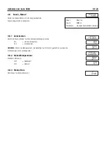
3.9 

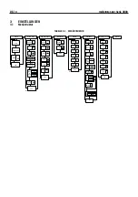
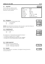
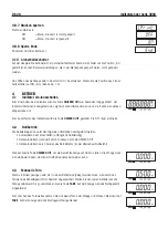
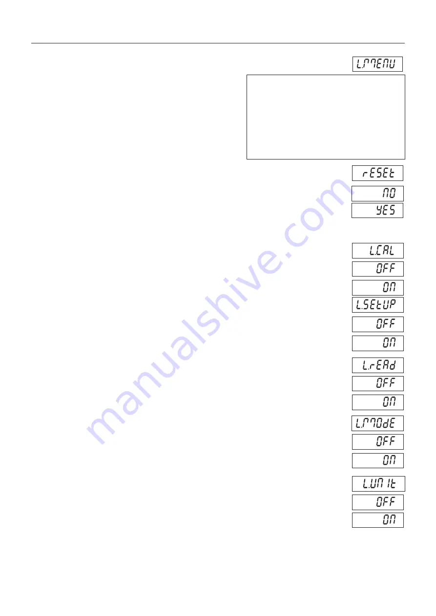
Menü „Menü sperren“

Rufen Sie dieses Menü auf. Die Standardeinstellungen 
erscheinen in Fettdruck.

3.9.1 Zurücksetzen

Setzt das Menü „Menü sperren“ auf die Werkseinstellungen zurück.
 

NO 

= nicht zurücksetz   en.

 YES = 

zurücksetzen.

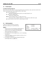
HINWEIS:

 Die Einstellungen für über LFT gesteuerte Menüelemente werden nicht zurückgesetzt.

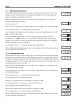
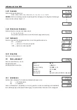
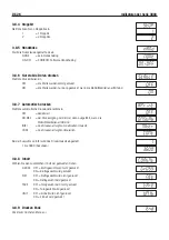
3.9.2 Kalibrierung sperren

Stellt den Status ein.
 

OFF 

= Menü „Kalibrierung“ ist nicht gesperrt.


ON 

= Menü „Kalibrierung“ ist gesperrt und ausgeblendet.

3.9.3 Setup sperren

Stellt den Status ein.
 

OFF 

= Menü „Setup“ ist nicht gesperrt.


ON 

= Menü „Setup“ ist gesperrt und ausgeblendet.

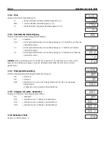
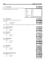
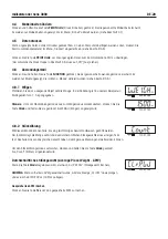
3.9.4 Ablesewert sperren

Stellt den Status ein.
 

OFF 

= Menü „Ablesewert“ ist nicht gesperrt.


ON 

= Menü „Ablesewert“ ist gesperrt und ausgeblendet.

3.9.5 Modus sperren

Stellt den Status ein.
 

OFF 

= Menü „Modus“ ist nicht gesperrt.

             ON 

= Menü „Modus“ ist gesperrt und ausgeblendet.

3.9.6  Einheit sperren

Stellt den Status ein.
 

OFF 

= Menü „Einheit“ ist nicht gesperrt.


ON 

= Menü „Einheit“ ist gesperrt und ausgeblendet.

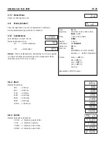
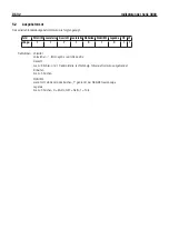
Reset:

No

, Yes

Lock Calibration Menu

Off

, On 

Lock Setup Menu

Off

, On 

Lock Readout Menu

Off

, On 

Lock Mode Menu

Off

, On 

Lock Unit Menu

Off

, On 

Lock Print Menu

Off

, On 

Menü „Lock“ (Sperren) beenden

Summary of Contents for Ranger 3000 Series

Page 1: ...i Indicatori serie 3000 Manuale di istruzioni Indicatore T31XW Indicatore T31P...

Page 2: ...ii...

Page 3: ...vono essere certificati in due fasi non recano la M verde metrologia sulla targa descrittiva ma solo il marchio di identificazione mostrato qui accanto sull etichetta della confezione La seconda fase...

Page 4: ...gitale di Classe A in conformit con la Parte 15 delle norme FCC Tali limiti sono previsti per fornire un adeguata protezione contro interferenze dannose durante il funzionamento dell apparecchiatura i...

Page 5: ...ntaggio diretto a parete solo modello T31P IT 13 2 6 Staffa di montaggio solo modello T31XW IT 13 3 IMPOSTAZIONI IT 14 3 1 Struttura dei menu IT 14 3 2 Navigazione nei menu IT 15 3 3 Menu Calibration...

Page 6: ...a in grammi IT 24 3 7 5 Ounce Unit Unit di misura in once IT 24 3 7 6 Pound Ounce Unit Unit di misura in libbre e once IT 24 3 7 7 End Unit Fine Unit di misura IT 24 3 8 Menu Print Stampa IT 25 3 8 1...

Page 7: ...eggio parti IT 29 5 COMUNICAZIONE SERIALE IT 31 5 1 Comandi interfaccia IT 31 5 2 Formato uscita IT 32 6 VALIDIT PER LE TRANSAZIONI COMMERCIALI LFT IT 33 6 1 Impostazioni IT 33 6 2 Certificazione IT 3...

Page 8: ...le Accertarsi che il cavo di alimentazione non rappresenti un potenziale ostacolo o non costituisca un intralcio al passaggio Utilizzare solo accessori e periferiche approvate Utilizzare l apparecchia...

Page 9: ...tore T31P 1 2 3 Voce Descrizione 1 Etichetta dati 2 Pannello anteriore 3 Pannello di controllo 4 Vite di sicurezza 5 Foro 4 per montaggio a parete 6 Vite 4 7 Etichetta dati 8 Pannello posteriore 9 Pre...

Page 10: ...4 Pannello di controllo 5 Staffa di montaggio 6 Vite 4 7 Pannello posteriore 8 Etichetta dati 9 Pressacavo per RS232 10 Pressacavo per cavo cella di carico 11 Cavo di alimentazione Figura 1 2 Indicat...

Page 11: ...nticello di rilevamento W1 5 Blocco terminale cella di carico J5 6 Ponticello di rilevamento W2 7 Blocco terminale RS232 J6 solo modello T31XW 8 Connettore RS232 J7 solo modello T31P 9 Interruttore LF...

Page 12: ...bra 3 Simbolo oncia 4 Simboli chilogrammi e grammi 5 Pulsante TARE Menu 6 Simbolo funzione TARE 7 Pulsante FUNCTION Mode 8 Simbolo funzione NET 9 Simbolo funzione PCS 10 Pulsante PRINTUnits 11 Simbolo...

Page 13: ...ssione lunga Off Spegnimento dell indicatore Units Modifica dell unit di misura Mode Modifica dell unit di misura Pressione prolungata scorrimento modalit Menu Accesso al menu User Funzione menu press...

Page 14: ...Foglio etichette di portata CD del manuale di istruzioni Scheda di garanzia Kit sigillatura LFT 2 2 Connessioni esterne 2 2 1 Cavo interfaccia RS232 modello T31P Collegare il cavo RS232 opzionale al c...

Page 15: ...lo della funzione batteria indica che la batteria quasi scarica e deve essere ricaricata Dal momento in cui il simbolo della batteria comincia a lampeggiare restano circa 60 minuti di autonomia L indi...

Page 16: ...eriore T31XW Rimuovere le quattro viti a testa esagonale dal pannello posteriore Aprire il pannello estraendo delicatamente in avanti il pannello anteriore Dopo aver effettuato tutte le connessioni ri...

Page 17: ...perficie su cui viene effettuato il montaggio La staffa adatta a viti di diametro fino a 6 mm 1 4 Individuare i fori di montaggio come mostrato in Figura 2 6 Figura 2 3 Configurazione per montaggio a...

Page 18: ...21 2 3281 6 21 2 5 06 21 2 281 6 21 2 3281 6 281 6 21 2 2817 21 2 6 783 1 5 6 7 6 12 7 2 21 1 3 1 02 21 2 6 87 2 2 6 7 6 7 6 7 1 2 35 17 872 35 17 2 1 1 RQWHQW 2Q 6WDEOH RQWLQXRXV 17 5 6 0 URVV 1HW 7D...

Page 19: ...di calibrazione 3 2 Navigazione nei menu PER ACCEDERE AL MENU MODALIT MODE Tenere premuto il pulsante Menu fino a quando sul display non viene visualizzato MENU Sul display viene visualizzato il prim...

Page 20: ...ualizza il valore effettivo della pesata 3 3 2 Linearity Calibration Calibrazione di linearit La calibrazione di linearit Linearity Calibration utilizza 3 punti di calibrazione Il primo punto di calib...

Page 21: ...are le variazioni della forza di gravit Nota la modifica del fattore GEO altera la calibrazione Il valore GEO stato impostato in fabbrica e deve essere modificato solo da un rappresentante autorizzato...

Page 22: ...6 17 16 16 15 15 14 14 13 13 12 12 43 26 44 32 17 17 16 16 15 15 14 14 13 13 12 44 32 45 38 18 17 17 16 16 15 15 14 14 13 13 45 38 46 45 18 18 17 17 16 16 15 15 14 14 13 46 45 47 51 19 18 18 17 17 16...

Page 23: ...ione Graduation all intervallo zero Zero Range e alla validit per le transazioni commerciali Legal For Trade non vengono ripristinate ai valori di fabbrica 3 4 4 Capacity Portata Impostazione della po...

Page 24: ...0 15 20 25 30 40 50 60 75 100 120 150 200 250 300 400 500 600 750 300 750 1000 0 05 0 1 0 2 0 5 1 0 2 0 5 1 5 10 15 20 25 30 40 50 60 75 100 120 150 200 250 300 400 500 600 750 1000 500 1000 1200 0 1...

Page 25: ...uto Shut Off Off End Readout Uscita dal menu READOUT 3 5 1 Reset Ripristino delle impostazioni di fabbrica Ripristino del menu lettura Readout alle impostazioni predefinite in fabbrica No non ripristi...

Page 26: ...are in posizione ON 3 5 4 Backlight Retroilluminazione Impostazione della funzionalit di retroilluminazione del display OFF sempre disattivata ON sempre attivata AUtO attivata alla pressione di un pul...

Page 27: ...vare le modalit di applicazione desiderate Reset No Yes Count Off On End Mode Exit MODE menu 3 6 1 Reset Ripristino delle impostazioni di fabbrica Ripristino del menu modalit Mode alle impostazioni di...

Page 28: ...i fabbrica Impostazioni NO non ripristina le impostazioni di fabbrica YES ripristina le impostazioni di fabbrica Se la voce di menu Validit delle transazioni commerciali LFT impostata su ON il riprist...

Page 29: ...tazioni di fabbrica YES ripristina le impostazioni di fabbrica 3 8 Menu Print Stampa Accedere a questo menu per definire i parametri di stampa Le impostazioni predefinite sono evidenziate Nota se la v...

Page 30: ...Impostazione della funzionalit di stampa automatica OFF disabilitato ON StAb la stampa viene effettuata ogni qualvolta vengono soddisfatti i criteri di stabilit INtEr la stampa viene effettuata in ba...

Page 31: ...3 9 2 Lock Calibration Blocco calibrazione Impostazione dello stato OFF il menu calibrazione Calibration non bloccato ON il menu calibrazione Calibration bloccato e non viene visualizzato 3 9 3 Lock...

Page 32: ...aneamente visualizza informazioni sul software e quindi accede alla modalit di pesata attiva Per spegnere l indicatore premere e tenere premuto il pulsante ON ZERO Off fino a visualizzare OFF 4 2 Funz...

Page 33: ...zzati o l invio dei dati a un computer richiede l impostazione dei parametri di comunicazione nel menu di stampa Print fare riferimento alla Sezione 3 8 Premere il pulsante PRINT Units per inviare i d...

Page 34: ...ata la grandezza del campione Put10Pcs Determinazione di un nuovo APW Premere il pulsante No per incrementare la grandezza del campione possibile scegliere 5 10 20 50 100 e 200 Per stabilire l APW col...

Page 35: ...visualizzato stabile o instabile P Stampa il peso visualizzato stabilmente in base alle impostazioni relative alla stabilit CP Stampa continua SP Stampa solo se il peso stabile xP Intervallo di stampa...

Page 36: ...ra senza zero iniziale Unit di misura fino a 5 caratteri Stabilit in caso di instabilit viene stampato il carattere in caso di stabilit uno spazio vuoto Leggenda fino a 5 caratteri G Lordo NET Netto T...

Page 37: ...ibrazione di ampiezza Span Calibration Calibrazione di linearit Linearity Calibration Unit di misura calibrazione Calibration Unit GEO LFT Portata Capacity Graduazione Graduation Intervallo zero Zero...

Page 38: ...tabile Contattare l assistenza tecnica Impossibile effettuare la calibrazione Blocco menu di calibrazione attivato Interruttore di blocco in posizione on Menu LFT attivato Valore non corretto del peso...

Page 39: ...s com per individuare l ufficio Ohaus pi vicino Errore 8 3 Lettura del peso superiore al limite di sovraccarico Ridurre il carico sulla bilancia Errore 8 4 Lettura del peso inferiore al limite di cari...

Page 40: ...ella portata Interfaccia RS232 Dimensioni complessive L x A x P mm pollici 8 2 x 2 8 x 6 5 210 x 71 x 168 8 3 x 2 8 x 5 8 212 x 71 x 149 Peso netto lb kg 3 6 1 6 6 6 2 9 Peso dell imballo lb kg 5 7 2...

Page 41: ...aio inox 35 cm 80251745 Kit di montaggio a colonna acciaio inox 70 cm 80251746 Kit di montaggio a parete T31P 80251747 Kit di montaggio a parete T31P 80251748 Cavo interfaccia PC 25 pin T31P 80500524...

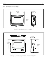
Page 42: ...ura 8 1 Dimensioni complessive Indicatore T31P Figura 8 2 Dati dimensionali dell indicatore T31XW con staffa di montaggio 239 mm 9 pollici 210 mm 8 2 pollici 168 mm 6 5 pollici 71 mm 2 8 pollici 71 mm...

Page 43: ...on applicabile se il prodotto stato danneggiato accidentalmente o a causa di utilizzo errato se stato esposto a materiali radioattivi o corrosivi se materiali esterni sono penetrati nel prodotto stess...

Page 44: ...s Corporation 19A Chapin Road P O Box 2033 Pine Brook NJ 07058 USA Tel 973 377 9000 Fax 973 593 0359 www ohaus com P N 80251133 B Ohaus Corporation 2008 tutti i diritti riservati Stampato in Cina 8025...

Page 45: ...i Manuel d instructions pour les indicateurs de la s rie 3000 Indicateur T31XW Indicateur T31P...

Page 46: ...ii...

Page 47: ...de pesage v rifier en deux tapes ne portent pas d autocollant M pour M trolologie en vert sur la plaque descriptive et portent l une des marques d identification pr c dentes sur l tiquette de l emball...

Page 48: ...ssion F d rale des communications Ces limites ont pour objectif de fournir une protection raisonnable contre toute interf rence dangereuse lorsque l quipement est utilis dans un environnement commerci...

Page 49: ...ble d interface RS232 T31XW FR 12 2 4 Orientation du couvercle arri re de T31P FR 13 2 5 Montage mural direct T31P uniquement FR 13 2 6 Support de montage T31XW uniquement FR 13 3 R GLAGES FR 14 3 1 S...

Page 50: ...Unit des livres onces FR 24 3 7 7 End Unit Fin unit FR 24 3 8 Menu Print Imprimer FR 25 3 8 1 Reset R initialiser FR 25 3 8 2 Baud FR 25 3 8 3 Parity FR 25 3 8 4 Stop Bit Bit d arr t FR 25 3 8 5 Hand...

Page 51: ...6 2 Parts Counting Comptage des pi ces FR 29 5 COMMUNICATION S RIE FR 31 5 1 Commandes de l interface FR 31 5 2 Format de sortie FR 32 6 M TROLOGIE L GALE FR 33 6 1 Param tres FR 33 6 2 V rification...

Page 52: ...ilisez uniquement les accessoires et les p riph riques approuv s Utilisez la balance uniquement dans les conditions ambiantes sp cifi es dans les pr sentes instructions D connectez l quipement de l al...

Page 53: ...P 1 2 3 TABLEAU 1 1 PI CES T31P 4 6 7 8 9 10 11 5 l ment Description 1 Libell des donn es 2 Bo tier avant 3 Panneau de commande 4 Vis de s curit 5 Clavette 4 pour un montage mural 6 Vis 4 7 Libell des...

Page 54: ...s pi ces et des commandes suite TABLEAU 1 2 PI CES T31XW l ment Description 1 Libell des donn es 2 Bo tier avant 3 Bouton de r glage 2 4 Panneau de commande 5 Support montage 6 Vis 4 7 Bo tier arri re...

Page 55: ...d le J4 T31XW uniquement 2 Connecteur de pile T31P uniquement 3 Entr e secteur 4 Cavalier de d tection W1 5 Bornier du capteur J5 6 Cavalier de d tection W2 7 Bornier RS232 mod le J6 T31Xw uniquement...

Page 56: ...13 14 5 N D signation 1 Fen tre de l tiquette de capacit 2 Symbole des livres 3 Symbole des onces 4 Symboles des kilogrammes grammes 5 Bouton Menu TARE 6 Symbole de fonction TARE 7 Bouton Mode FUNCTI...

Page 57: ...ermet de changer l unit de pesage Mode Permet de changer le mode d application Appuyez sur le bouton et maintenez le en fonc pour faire d filer les modes Menu Active le menu User Fonction de menu appu...

Page 58: ...e sceau de m trologie l gale 2 2 Connexions externes 2 2 1 C ble d interface RS232 T31P Connectez le c ble RS232 optionnel au connecteur RS232 Figure 1 1 l ment 13 2 2 2 Alimentation CA T31P Connectez...

Page 59: ...le un triangle clignotant situ au dessus du symbole de la pile indique que la pile est faible et qu il faut la recharger Lorsque le symbole se met clignoter il reste environ 60 minutes de fonctionneme...

Page 60: ...ir l tanch it Broche Connexion J5 1 EXC J5 2 SENS J5 3 SIG J5 4 GND J5 5 SIG J5 6 SENS J5 7 EXC Connexions des cavaliers Pour un capteur 4 fils sans fils de d tection les cavaliers W2 et W3 doivent tr...

Page 61: ...ide de fixations non fournies appropri es au type de surface de montage Le sup port convient des vis d un diam tre allant jusqu 6 mm 1 4 po Rep rez les trous de montage voir la Figure 2 6 Figure 2 3 C...

Page 62: ...2 3281 6 21 2 5 06 21 2 281 6 21 2 3281 6 281 6 21 2 2817 21 2 6 783 1 5 6 7 6 12 7 2 21 1 3 1 02 21 2 6 87 2 2 6 7 6 7 6 7 1 2 35 17 872 35 17 2 1 1 RQWHQW 2Q 6WDEOH RQWLQXRXV 17 5 6 0 URVV 1HW 7DUH...

Page 63: ...dant le processus POUR ACTIVER LE MODE DE MENU PROC DEZ COMME SUIT Appuyez sur le bouton Menu que vous maintenez enfonc jusqu ce que MENU s affiche Le premier menu du niveau sup rieur s affiche R capi...

Page 64: ...de port e a r ussi la balance passe au mode de pesage actif et affiche la valeur r elle du poids 3 3 2 Calibrage de lin arit Le calibrage de lin arit se sert de 3 points Le premier point de calibrage...

Page 65: ...rque Le changement du facteur g ographique modifie le calibrage La valeur GEO a t d finie l usine et seul un repr sentant agr par le fabricant ou un personnel agr responsable du contr le est autoris l...

Page 66: ...3 12 12 11 42 19 43 26 17 16 16 15 15 14 14 13 13 12 12 43 26 44 32 17 17 16 16 15 15 14 14 13 13 12 44 32 45 38 18 17 17 16 16 15 15 14 14 13 13 45 38 46 45 18 18 17 17 16 16 15 15 14 14 13 46 45 47...

Page 67: ...Plage de z ro et Legal For Trade M trologie l gale ne sont pas r initialis s 3 4 4 Capacity D finissez la capacit de la balance de 5 20 000 Voir le tableau de configuration 3 3 pour obtenir les param...

Page 68: ...0 2 0 5 5 10 15 20 25 30 40 50 60 75 100 120 150 200 250 300 400 500 600 750 300 750 1000 0 05 0 1 0 2 0 5 1 0 2 0 5 1 5 10 15 20 25 30 40 50 60 75 100 120 150 200 250 300 400 500 600 750 1000 500 10...

Page 69: ...R initialiser Si l option Legal for Trade M trologie l gale est d finie sur ON les param tres de Stable Range Plage stable Averaging Level Niveau de la moyenne Auto Zero Tracking Suivi Auto Z ro et Au...

Page 70: ...N 3 5 4 Backlight R tro clairage Permet d activer le r tro clairage de l affichage OFF Toujours d sactiv ON Toujours activ AUtO S active lorsqu un bouton est appuy ou que le poids affich change D sact...

Page 71: ...asser au menu suivant 3 6 Menu Mode Activez ce menu pour utiliser les modes d applications souhait s Reset No Yes Count Off On End Mode Exit MODE menu 3 6 1 Reset R initialiser Permet de restaurer les...

Page 72: ...er les valeurs par d faut du menu Unit Param tres NO Pas de r initialisation YES R initialiser Si l option du menu Legal for Trade M trologie l gale est activ e les param tres ne sont pas r initialis...

Page 73: ...t du menu Print NO Pas de r initialisation YES R initialiser 3 8 Menu Print Imprimer Activez ce menu permettant de d finir les param tres d impression Les param tres par d faut sont en caract res gras...

Page 74: ...8 6 Print Stable Data Only Imprimer donn es stables uniquement Permet de d finir les crit res d impression OFF Les valeurs sont imm diatement imprim es ON Les valeurs ne sont imprim es que lorsque les...

Page 75: ...alibration Verrouiller le calibrage Permet de d finir le statut OFF Le menu de calibrage n est pas verrouill ON Le menu Calibration est verrouill et masqu 3 9 3 Lock Setup Verrouiller la configuration...

Page 76: ...iquant pendant quelques instants la version du logiciel et passe ensuite en mode de pes e actif Pour d sactiver l indicateur appuyez sur le bouton ON ZERO Off que vous maintenez enfonc jusqu ce que l...

Page 77: ...vers une imprimante ou la transmission de donn es vers un ordinateur requiert que les param tres de communication dans le menu Print Imprimer soient d finis voir la Section 3 8 Appuyez sur le bouton...

Page 78: ...e indique maintenant la taille de l chantillon Put10Pcs D finition d un nouveau poids moyen des pi ces Appuyez sur le bouton No pour augmenter la taille de l chantillon Les choix sont 5 10 20 50 100 e...

Page 79: ...tour de chariot CR ou un retour de chariot passage la ligne CRLF Les donn es produites par l indicateur doivent toujours se terminer par un retour de chariot passage la ligne CRLF Caract re de command...

Page 80: ...t Le signe s imprime si n gative vide si positive Poids Jusqu 6 nombres et 1 d cimale align droite z ro gauche clignotant Unit de mesure Jusqu 5 caract res Stabilit Le caract re s imprime si instable...

Page 81: ...ts ne sont pas modifiables Span Calibration Linearity Calibration Calibration Unit GEO LFT Capacity Graduation Zero Range Stable Range AZT Modes Units Pour activer l dition de ces param tres remettez...

Page 82: ...est pas stable Capteurs endommag s Enlevez la charge de la balance Attendez que la charge soit stable Service requis Impossible de calibrer L option Lock Calibration Menu Verrouiller le menu de calibr...

Page 83: ...2 Affichage du poids inf rieur la limite du z ro de mise sous tension Ajoutez une charge la balance Calibrez nouveau la balance Erreur 8 3 Affichage du poids sup rieur la limite de surcharge R duisez...

Page 84: ...ctions Pesage comptage des pi ces Affichage Hauteur des chiffres 1 po 2 5 mm 6 chiffres 7 segments LCD r tro clairage 1 5 po 3 8 cm de haut x 4 9 po 12 5 cm de large R tro clairage LED blanche Clavier...

Page 85: ...45 Kit de montage sur colonne 70 cm acier inoxydable 80251746 Kit de montage mural T31P 80251747 Kit de montage mural T31XW 80251748 C ble interface Ordinateur 25 broches T31P 80500524 C ble interface...

Page 86: ...mensions Figure 8 1 Dimensions globales de l indicateur T31P Figure 8 2 Dimensions globales de l indicateur T31XW avec support de montage 210 mm 8 2 po 77 mm 2 8 po 168 mm 6 5 po 239 mm 9 po 212 mm 8...

Page 87: ...on e a t expos des mat riaux radioactifs ou corrosifs contient des mat riaux trangers ayant p n tr l int rieur ou suite un service ou une modification apport e par des techniciens autres que Ohaus la...

Page 88: ...haus Corporation 19A Chapin Road P O Box 2033 Pine Brook NJ 07058 USA Tel 973 377 9000 Fax 973 593 0359 www ohaus com P N 80251131 B Ohaus Corporation 2008 tous droits r serv s Imprim en Chine 8025113...

Page 89: ...i Indicadores serie 3000 Manual de instrucciones Indicador T31XW Indicador T31P...

Page 90: ...ii...

Page 91: ...de pesaje que se verifican en dos etapas no tienen la etiqueta de metrolog a M de color verde en la placa descriptiva y no sustentan una de las marcas de identificaci n en la etiqueta del empaque La...

Page 92: ...la FCC Estos l mites est n dise ados para proporcionar una protecci n razonable contra interferencia da ina cuando el equipo es operado en un ambiente comercial Este equipo genera usa y puede irradia...

Page 93: ...para el T31P o el T31XW ES 12 2 3 3 Cable de interfase RS232 para el T31XW ES 12 2 4 Orientaci n de la tapa posterior del T31P ES 13 2 5 Montaje directo en la pared s lo para el T31P ES 13 2 6 Soporte...

Page 94: ...nidad de gramos ES 24 3 7 5 Unidad de onzas ES 24 3 7 6 Unidad de libras onza ES 24 3 7 7 Terminar unidad ES 24 3 8 Men de impresi n ES 25 3 8 1 Reiniciar ES 25 3 8 2 Baudios ES 25 3 8 3 Paridad ES 25...

Page 95: ...6 2 Conteo de partes ES 29 5 COMUNICACI N SERIAL ES 31 5 1 Se ales de interfase ES 31 5 2 Formato de salida ES 32 6 LEGAL PARA EL COMERCIO ES 33 6 1 Configuraciones ES 33 6 2 Verificaci n ES 33 6 3 S...

Page 96: ...st culo potencial o riesgo de tropezarse Use s lo accesorios y perif ricos aprobados Opere el equipo s lo en las condiciones ambientales especificadas en estas instrucciones Desconecte el equipo de la...

Page 97: ...31P 4 6 7 8 9 10 11 5 Parte Descripci n 1 Etiqueta de informaci n 2 Parte frontal 3 Panel de control 4 Tornillo de seguridad 5 Orificio gu a 4 para montaje en pared 6 Tornillo 4 7 Etiqueta de informac...

Page 98: ...t TABLA 1 2 PARTES DEL T31XW Parte Descripci n 1 Etiqueta de informaci n 2 Parte frontal 3 Perilla de ajuste 2 4 Panel de control 5 Soporte de montaje 6 Tornillo 4 7 Parte posterior 8 Etiqueta de info...

Page 99: ...3 L nea de entrada de corriente 4 Conexi n en puente W1 de detecci n 5 Bloque de terminales J5 de la celda de carga 6 Conexi n en puente W2 de detecci n 7 Bloque de terminales J7 del RS232 s lo para...

Page 100: ...ci n de capacidad 2 S mbolo de libras 3 S mbolo de onzas 4 S mbolos de kilogramos y gramos 5 Bot n de men de tara 6 S mbolo de funci n de tara 7 Bot n de funci n de modo 8 S mbolo de funci n de peso n...

Page 101: ...la unidad de pesaje Mode Permite cambiar el modo de la aplicaci n Si se presiona y mantiene as permite desplazarse por los diferentes modos Menu Ingresa al men de usuario Funci n de men presi n corta...

Page 102: ...os legal para el comercio 2 2 Conexiones externas 2 2 1 Cable de interfase RS232 con el T31P Conecte el cable opcional RS232 con el conector RS232 Figura 1 1 parte 13 2 2 2 Corriente alterna para el T...

Page 103: ...stellante que est arriba del s mbolo de funci n de la bater a indica que la bater a est baja y requiere recarga Cuando el s mbolo de la bater a comienza a destellar quedar n aproximadamente 60 minutos...

Page 104: ...ire los cuatro tornillos hexagonales de la parte posterior de la caja Abra la caja con cuidado tirando de la parte superior de la parte anterior hacia adelante Una vez que est n hechas todas las conex...

Page 105: ...ipo de superficie de montaje El soporte puede fijarse con tornillos de hasta 6 mm 1 4 de di metro Identifique los orificios de montaje como se ilustra en la Figura 2 6 Figura 2 3 Configuraci n para mo...

Page 106: ...21 2 3281 6 21 2 5 06 21 2 281 6 21 2 3281 6 281 6 21 2 2817 21 2 6 783 1 5 6 7 6 12 7 2 21 1 3 1 02 21 2 6 87 2 2 6 7 6 7 6 7 1 2 35 17 872 35 17 2 1 1 RQWHQW 2Q 6WDEOH RQWLQXRXV 17 5 6 0 URVV 1HW 7...

Page 107: ...rante aproximadamente 5 minutos despu s de haberse estabilizado a temperatura ambiente 5 Para cancelar la calibraci n presione el bot n Exit en cualquier momento durante la calibraci n PARA INGRESAR E...

Page 108: ...ibraci n de extensi n la b scula sale al modo de pesaje activo y muestra el valor del peso actual 3 3 2 Calibraci n de linealidad La calibraci n de linealidad utiliza tres puntos de calibraci n El pri...

Page 109: ...dad Nota El cambio del factor GEO altera la calibraci n El factor GEO se configura en la f brica y solamente un representante autorizado del fabricante o personal certificado de verificaci n pueden ca...

Page 110: ...2 11 42 19 43 26 17 16 16 15 15 14 14 13 13 12 12 43 26 44 32 17 17 16 16 15 15 14 14 13 13 12 44 32 45 38 18 17 17 16 16 15 15 14 14 13 13 45 38 46 45 18 18 17 17 16 16 15 15 14 14 13 46 45 47 51 19...

Page 111: ...en ON las configuraciones de capacidad graduaci n rango cero y legal para el comercio no se reinician 3 4 4 Capacidad Establece la capacidad de la b scula entre 5 y 20000 Consulte las configuraciones...

Page 112: ...25 30 40 50 60 75 100 120 150 200 250 300 400 500 600 750 300 750 1000 0 05 0 1 0 2 0 5 1 0 2 0 5 1 5 10 15 20 25 30 40 50 60 75 100 120 150 200 250 300 400 500 600 750 1000 500 1000 1200 0 1 0 2 0 5...

Page 113: ...idad de presentaci n Reset No Yes Filter Level Lo Med Hi Auto Zero Tracking Off 0 5d 1d 3d Backlight Off On Auto Auto Shut Off Off End Readout Salir del men READOUT 3 5 1 Reiniciar Restablece los valo...

Page 114: ...en la posici n de habilitaci n 3 5 4 Luz de fondo Establece la funcionalidad de la luz de fondo de la pantalla OFF siempre apagada ON siempre encendida AUtO se enciende cuando se presiona alg n bot n...

Page 115: ...al siguiente men 3 6 Men de modos Ingrese en este men para activar los modos de aplicaci n deseados Reset No Yes Count Off On End Mode Salir del men MODE 3 6 1 Reiniciar Restablece los valores de f br...

Page 116: ...lece los valores de f brica del men de unidades Unit Configuraciones NO no restablecer YES restablecer Si el men LTF est configurado en ON las configuraciones no se restablecen Reset No Yes Kilograms...

Page 117: ...ores de f brica NO no restablecer YES restablecer 3 8 Men de impresi n Ingrese en este men para definir los par metros de impresi n Las configuraciones de f brica est n en negritas Nota Si el men LTF...

Page 118: ...de impresi n Print Interval 1 a 3600 segundos 3 8 6 Imprimir solamente datos estables Establece el criterio de impresi n OFF los valores se imprimen inmediatamente ON los valores se imprimen solament...

Page 119: ...no se restablecen 3 9 2 Bloquear calibraci n Establece el estado OFF No se bloquea el men de calibraci n ON El men de calibraci n se bloquea y se oculta 3 9 3 Bloquear configuraci n Establece el estad...

Page 120: ...realiza una prueba de pantalla presenta moment neamente la versi n de software e ingresa en el modo de pesaje activo Para apagar el indicador mantenga presionado el bot n ON ZERO Off hasta que aparezc...

Page 121: ...v o de datos a una computadora requiere que se establezcan los par metros de comunicaci n en el men de impresi n consulte la Secci n 3 8 Presione el bot n PRINT Units para enviar los datos mostrados a...

Page 122: ...e el bot n No para incrementar el tama o de la muestra Las opciones son 5 10 20 50 100 y 200 Para establecer el APW coloque la cantidad especificada de muestras sobre la b scula y presione el bot n Ye...

Page 123: ...un retorno de carro CR o retorno de carro l nea de alimentaci n CRLF La salida de datos a trav s del indicador siempre se termina con un retorno de carro l nea de alimentaci n CRLF Car cter de se al F...

Page 124: ...s Polaridad signo si es negativa en blanco si es positiva Peso hasta 6 n meros y 1 decimal justificado a la derecha cero inicial destellando Unidades hasta 5 caracteres Estabilidad se imprime el car c...

Page 125: ...raci n de extensi n calibraci n de linealidad unidad de calibraci n GEO LFT capacidad graduaci n rango cero rango estable y unidades Para habilitar la edici n de estas configuraciones de men regrese e...

Page 126: ...en la b scula no es estable Da o de la celda de carga Retire la carga de la b scula Espere que se estabilice la carga Se requiere servicio No puede calibrarse El men de bloqueo de calibraci n Lock Cal...

Page 127: ...encendido Retire la carga de la b scula Vuelva a calibrar la b scula Error 8 2 La lectura del peso est por debajo del l mite de cero de encendido Aumente la carga de la b scula Vuelva a calibrar la b...

Page 128: ...a celda de carga Hasta 3 mV V Tiempo de estabilizaci n Dentro de 2 segundos Seguimiento de cero autom tico Off 0 5 1 3 divisiones Rango de cero 0 2 100 de la capacidad Calibraci n de extensi n 5 kg o...

Page 129: ...oxidable 80251745 Juego de montaje en columna 70 cm acero inoxidable 80251746 Juego de montaje en pared T31P 80251747 Juego de montaje en pared T31XW 80251748 Interfase cable PC 25 patillas T31P 80500...

Page 130: ...s Figura 8 1 Dimensiones generales del indicador T31P Figura 8 2 Dimensiones generales del indicador T31XW con soporte de montaje 210 mm 8 2 pulg 168 mm 6 5 pulg 71 mm 2 8 pulg 239 mm 9 pulg 212 mm 8...

Page 131: ...da ado por accidente o mal uso expuesto a sustancias radioactivas o corrosivas si presenta material extra o penetrando en el interior del producto o como resultado de un servicio o modificaci n hecha...

Page 132: ...rporation 19A Chapin Road P O Box 2033 Pine Brook NJ 07058 USA Tel 973 377 9000 Fax 973 593 0359 www ohaus com P N 80251130 B Ohaus Corporation 2008 todos los derechos reservados Impreso en la China 8...

Page 133: ...3000 Series Indicators Instruction Manual T31P Indicator T31XW Indicator...

Page 134: ......

Page 135: ...ousing EN 11 2 3 2 Scale Base to T31P or T31XW EN 12 2 3 3 RS232 Interface Cable to T31XW EN 12 2 4 T31P Rear Cover Orientation EN 13 2 5 Direct Wall Mounting T31P only EN 13 2 6 Mounting Bracket T31X...

Page 136: ...m Unit EN 24 3 7 3 Pound Unit EN 24 3 7 4 Gram Unit EN 24 3 7 5 Ounce Unit EN 24 3 7 6 Pound Ounce Unit EN 24 3 7 7 End Unit EN 24 3 8 Print Menu EN 25 3 8 1 Reset EN 25 3 8 2 Baud EN 25 3 8 3 Parity...

Page 137: ...ng EN 29 5 SERIAL COMMUNICATION EN 31 5 1 Interface Commands EN 31 5 2 Output Format EN 32 6 LEGAL FOR TRADE EN 33 6 1 Settings EN 33 6 2 Verification EN 33 6 3 Sealing EN 33 6 3 1 Physical Seals EN 3...

Page 138: ...stacle or tripping hazard Use only approved accessories and peripherals Operate the equipment only under ambient conditions specified in these instructions Disconnect the equipment from the power supp...

Page 139: ...sing 3 Control Panel 4 Security Screw 5 Key Hole 4 for wall mounting 6 Screw 4 7 Data Label 8 Rear Housing 9 Power Receptacle 10 Strain Relief for Load Cell Cable 11 RS232 Connector TABLE 1 1 T31P PAR...

Page 140: ...4 7 Rear Housing 8 Data Label 9 Strain Relief for RS232 10 Strain Relief for Load Cell Cable 11 Power cord Figure 1 2 T31XW Indicator 2 3 5 6 7 8 9 10 11 1 2 Overview of Parts and Controls Cont TABLE...

Page 141: ...ly 3 Line Power Input 4 Sense Jumper W1 5 Load Cell Terminal Block J5 6 Sense Jumper W2 7 RS232 Terminal Block J7 T31XW Model only 8 RS232 Connector J6 T31P Model only 9 LFT On Off Switch TABLE 1 3 MA...

Page 142: ...Capacity Label Window 2 TARE Menu button 3 TARE symbol 4 FUNCTION Mode button 5 NET symbol 6 PCS symbol 7 PRINT Units button 8 Calibration Mode symbol 9 Battery symbol T31P only 10 ON ZERO Off button...

Page 143: ...ng the application mode Press and hold allows scrolling through modes Menu Enter the User menu View the Audit Trail event counters extended press Menu Function Short Press Yes Accepts the current sett...

Page 144: ...Kit 2 2 External Connections 2 2 1 RS232 interface Cable to T31P Connect the optional RS232 cable to the RS232 connector Figure 1 1 item 13 2 2 2 AC Power to T31P Connect the AC Adapter to the power...

Page 145: ...eration a flashing triangle above the battery function symbol indicates the battery is low and requires recharging Approximately 60 minutes of operation will remain when the battery symbol starts to b...

Page 146: ...e strain relief to ensure a watertight seal Pin Connection J5 1 EXCITATION J5 2 SENSE J5 3 SIGNAL J5 4 GND J5 5 SIGNAL J5 6 SENSE J5 7 EXCITATION Jumper Connections For a 4 wire load cell with no sens...

Page 147: ...W only Attach the bracket to a wall or table using fasteners not supplied that are appropriate for the type of mounting surface The bracket will accommodate up to 6 mm 1 4 diameter screws Locate the m...

Page 148: ...DE POUND 7 EVEN LOCK SETUP KILOGRAM O R E Z O T U A OFF 7 ODD OFF POUND F F O ON 7 NONE ON CAPACITY 0 5d GRAM 8 NONE LOCK READOUT 5 20000 d 1 OFF STOP OFF GRADUATION d 3 ON 1 ON 0 001 20 EXPAND MODE O...

Page 149: ...mately 5 minutes after stabilizing to room temperature 5 To abort calibration press the Exit button anytime during the calibration process TO ENTER THE MENU MODE Press and hold the Menu button until M...

Page 150: ...exits to the active weighing mode and displays the actual weight value 3 3 2 Linearity Calibration Linearity calibration uses 3 calibration points The first calibration point is established with no we...

Page 151: ...s in gravity Note Changing the GEO Factor alters the calibration The GEO value was set at the factory and should only be changed by an authorized manufacturer s representative or certified veriricatio...

Page 152: ...15 14 14 13 13 12 12 11 11 41 12 42 19 16 16 15 15 14 14 13 13 12 12 11 42 19 43 26 17 16 16 15 15 14 14 13 13 12 12 43 26 44 32 17 17 16 16 15 15 14 14 13 13 12 44 32 45 38 18 17 17 16 16 15 15 14 14...

Page 153: ...for Trade menu item is set to ON the Capacity Graduation Zero Range and Legal For Trade settings are not reset 3 4 4 Capacity Set the scale capacity from 5 to 20000 Refer to the Setup Table 3 3 for a...

Page 154: ...750 0 05 0 1 0 2 0 5 0 2 0 5 5 10 15 20 25 30 40 50 60 75 100 120 150 200 250 300 400 500 600 750 300 750 1000 0 05 0 1 0 2 0 5 1 0 2 0 5 1 5 10 15 20 25 30 40 50 60 75 100 120 150 200 250 300 400 50...

Page 155: ...customize display functionality Reset No Yes Filter Level Lo Med Hi Auto Zero Tracking Off 0 5d 1d 3d Backlight Off On Auto Auto Shut Off Off End Readout Exit READOUT menu 3 5 1 Reset Set the Readout...

Page 156: ...the hardware lock switch is set to the ON position 3 5 4 Backlight Set the display backlight functionality OFF always off ON always on AUtO turns on when a button is pressed or the displayed weight ch...

Page 157: ...Mode Advance to the next menu 3 6 Mode Menu Enter this menu to activate the desired application modes Reset No Yes Count Off On End Mode Exit MODE menu 3 6 1 Reset Set the Mode menu to the factory def...

Page 158: ...t Set the Unit menu to the factory defaults Settings NO not reset YES reset If the Legal for Trade menu item is set ON the settings are not reset Reset No Yes Kilograms Off On Pounds Off On Grams Off...

Page 159: ...RINT menu 3 8 1 Reset Set the Print menu to factory defaults NO not reset YES reset 3 8 Print Menu Enter this menu to define printing parameters Default settings are bold NOTE If the Legal for Trade m...

Page 160: ...erval 1 to 3600 seconds 3 8 6 Print Stable Data Only Set the print critera OFF values are printed immediately ON values are only printed when the stability criteria are met 3 8 4 Stop Bit Set the numb...

Page 161: ...tings for LFT controlled menu items are not reset 3 9 2 Lock Calibration Set the status OFF Calibration menu is not locked ON Calibration menu is locked and hidden 3 9 3 Lock Setup Set the status OFF...

Page 162: ...he software version and then enters the active weighing mode To turn the Indicator off press and hold the ON ZERO Off button until OFF is displayed 4 2 Zero Operation Zero can be set under the followi...

Page 163: ...or sending the data to a computer requires that the communication parameters in the Print Menu are set refer to Section 3 8 Press the PRINT Units button to send the displayed data to the communication...

Page 164: ...e Weight APW The display shows Put10 Pcs Establishing a New APW Press the No button to increment the sample size Choices are 5 10 20 50 100 and 200 To establish the APW place the specified quantity of...

Page 165: ...displayed weight stable or unstable P Print stable displayed weight according to stability setting CP Continuous Print SP Print when stable xP Interval Print x Print Interval 1 3600 sec Z Same as pres...

Page 166: ...decimal right justified leading zero blanking Units up to 5 characters Stability character is printed if not stable blank if stable Legend up to 3 characters G gross weight NET net weight T tare The...

Page 167: ...rity switch may be set to ON to safeguard against unintentional changes to configuration and calibration settings NOTE When Legal for Trade is set to ON and the security switch is set to ON the follow...

Page 168: ...raduation Power On Unit Zero Range Auto Zero Tracking Expanded Mode Count Mode Kilogram Unit Pound Unit Gram Unit Ounce Unit Pound Ounce Unit Stable Only Note that the counter only indexes once even i...

Page 169: ...EN 35 3000 Series Indicators The audit trail information is displayed in the format CFGxxx and CALxxx Then the indicator returns to normal operation CALIBRATION MODE CALIBRATION MODE CALIBRATION MODE...

Page 170: ...ot zero when turned on Load on Scale exceeds allowable limits Load on Scale is not stable Load Cell damage Remove load on Scale Wait for load to become stable Service required Unable to calibrate Lock...

Page 171: ...or Calibration value outside allowable limits Repeat calibration using correct calibration weights LOW rEF The average piece weight of the parts is small warning Use parts with average piece weight gr...

Page 172: ...s Weighing Parts Counting Display 1 in 2 5 cm digit height 6 digit 7 segment 1 5 in 3 8 cm high x 4 9 in 12 5 cm wide backlit LCD Backlight White LED Keypad 4 button mechanical switches 4 button membr...

Page 173: ...Kit 70 cm painted steel 80251744 Column Mount Kit 35 cm stainless steel 80251745 Column Mount Kit 70 cm stainless steel 80251746 Wall Mount Kit T31P 80251747 Wall Mount Kit T31XW 80251748 Interface C...

Page 174: ...EN 40 3000 Series Indicators 8 3 Drawings and Dimensions Figure 8 1 T31P Indicator Overall Dimensions Figure 8 2 T31XW Indicator Overall Dimensions with Mounting Bracket...

Page 175: ...l and the green M metrology sticker on the descriptive data plate They may be put into service immediately Weighing Instruments to be verified in two stages have no green M metrology on the descriptiv...

Page 176: ...o www ohaus com choose your country then search for WEEE Thank you for your contribution to environmental protection FCC Note This equipment has been tested and found to comply with the limits for a C...

Page 177: ...d by accident or misuse exposed to radioactive or corrosive materials has foreign material penetrating to the inside of the product or as a result of service or modification by other than Ohaus In lie...

Page 178: ...Ohaus Corporation 7 Campus Drive Suite 310 Parsippany NJ 07054 USA Tel 973 377 9000 Fax 973 944 7177 www ohaus com P N 80251064 E 2012 Ohaus Corporation all rights reserved Printed in China 80251064...

Page 179: ...i Bedienungsanleitung f r Indikatoren der Serie 3000 T31XW Indikator T31P Indikator...

Page 180: ...ii...

Page 181: ...fiziert werden m ssen befindet sich auf dem Schild mit der Beschreibung kein gr ner M Aufkleber Messtechnik und sie tragen eine der oben aufgef hrten Identifikationsmarkierungen auf dem Verpackungseti...

Page 182: ...Klasse A Diese Grenzen dienen dazu einen angemessenen Schutz gegen sch dliche St rstrahlungen zu bieten wenn das Ger t in einer gewerblichen Umgebung betrieben wird Dieses Ger t erzeugt verwendet und...

Page 183: ...11 2 3 2 W gebr cke zum T31P oder T31XW DE 12 2 3 3 RS232 Schnittstellenkabel zum T31XW DE 12 2 4 Ausrichtung der hinteren Abdeckung des T31P DE 13 2 5 Direkte Wandmontage nur T31P DE 13 2 6 Montagewi...

Page 184: ...inheit Pfund lbs DE 24 3 7 4 Einheit Gramm DE 24 3 7 5 Einheit Unze DE 24 3 7 6 Einheit Pfund Unze lbs oz DE 24 3 7 7 Einheit Ende DE 24 3 8 Men Drucken DE 25 3 8 1 Zur cksetzen DE 25 3 8 2 Baud DE 25...

Page 185: ...t ckz hlung DE 29 5 SERIELLE KOMMUNIKATION DE 31 5 1 Schnittstellenbefehle DE 31 5 2 Ausgabeformat DE 32 6 EICHPFLICHTIG DE 33 6 1 Einstellungen DE 33 6 2 Verifizierung DE 33 6 3 Versiegeln DE 33 7 WA...

Page 186: ...und Peripherieger te verwendet werden Nehmen Sie das Ger t nur dann in Betrieb wenn die Umgebungsbedingungen den in diesen Anweisungen aufgef hrten Bedingungen entsprechen Vor der Reinigung muss das...

Page 187: ...dikator 1 2 3 TABELLE 1 1 TEILE DES T31P 4 6 7 8 9 10 11 5 Artikel Beschreibung 1 Datenetikett 2 Vordergeh use 3 Bedienfeld 4 Sicherheitsschraube 5 Keilnut 4 f r die Wandmontage 6 Schraube 4 7 Datenet...

Page 188: ...blick ber Teile und Bedienelemente Forts TABELLE 1 2 TEILE DES T31XW Artikel Beschreibung 1 Datenetikett 2 Vordergeh use 3 Verstellknopf 2 4 Bedienfeld 5 Montagehalterung 6 Schraube 4 7 Hinteres Geh u...

Page 189: ...ss J4 nur Modell T31XW 2 Batterieanschluss nur T31P 3 Netzstromeingang 4 Abtastung Drahtbr cke W1 5 W gezellenklemmenblock J5 6 Abtastung Drahtbr cke W2 7 RS232 Klemmenblock J7 nur Modell T31XW 8 RS23...

Page 190: ...TABELLE 1 4 BEDIENFELD 13 14 5 Nr Bezeichnung 1 Kapazit tsaufkleberfenster 2 Pfund Symbol lbs 3 Unzensymbol 4 Symbole f r Kilogramm Gramm 5 TARE Menu Taste 6 TARE Funktionssymbol 7 FUNCTION Mode Taste...

Page 191: ...tet den Indikator aus Units ndert die W geeinheit Mode Erm glicht das ndern des Anwendungsmodus Durch Dr cken und Halten der Taste wird durch die Modi gebl ttert Menu Ruft das Benutzermen auf Men funk...

Page 192: ...ss 7 Kein Anschluss 8 Kein Anschluss 9 Kein Anschluss Abbildung 2 1 RS232 Stifte 2 INSTALLATION 2 1 Auspacken Packen Sie folgende Komponenten aus T31P oder T31XW Indikator Netzadapter nur T31P Montage...

Page 193: ...t ein blinkendes Dreieck ber dem Batteriefunktionssymbol an dass die Batterie schwach ist und wieder aufgeladen werden muss Wenn das Batteriesymbol zu blinken beginnt verbleiben noch ca 60 Minuten Bet...

Page 194: ...bschluss zu gew hrleisten Stift Verbindung J5 1 EXC J5 2 SENS J5 3 SIG J5 4 GND J5 5 SIG J5 6 SENS J5 7 EXC Drahtbr ckenanschl sse F r eine 4 adrige W gezelle ohne Abtastdr hte Drahtbr cken W2 und W3...

Page 195: ...n einer Wand oder einem Tisch In den Winkel k nnen Schrauben bis zu einer Gr e von 6 mm 1 4 eingebaut werden Lokalisieren Sie die in Abbildung 2 6 dargestellten Montagel cher Abbildung 2 3 Wandmontage...

Page 196: ...2 3281 6 21 2 5 06 21 2 281 6 21 2 3281 6 281 6 21 2 2817 21 2 6 783 1 5 6 7 6 12 7 2 21 1 3 1 02 21 2 6 87 2 2 6 7 6 7 6 7 1 2 35 17 872 35 17 2 1 1 RQWHQW 2Q 6WDEOH RQWLQXRXV 17 5 6 0 URVV 1HW 7DUH...

Page 197: ...st 4 Lassen Sie den Indikator ca 5 Minuten aufw rmen nachdem er sich auf Raumtemperatur stabilisiert hat 5 Zum Abbrechen der Kalibrierung dr cken Sie jederzeit w hrend des Kalibrierungsverfahrens auf...

Page 198: ...aktiven W gemodus zur ck und zeigt den tats chlichen Gewichtswert an 3 3 2 Linearit tskalibrierung Bei der Linearit tskalibrierung werden 3 Kalibrierungspunkte verwendet Der erste Kalibrierungspunkt w...

Page 199: ...die nderung des GEO Faktors wird die Kalibrierung modifiziert Der GEO Wert wurde ab Werk festgelegt und sollte nur von einem dazu befugten Vertreter des Herstellers oder einem zertifizierten Verifizi...

Page 200: ...2 19 43 26 17 16 16 15 15 14 14 13 13 12 12 43 26 44 32 17 17 16 16 15 15 14 14 13 13 12 44 32 45 38 18 17 17 16 16 15 15 14 14 13 13 45 38 46 45 18 18 17 17 16 16 15 15 14 14 13 46 45 47 51 19 18 18...

Page 201: ...erden die Einstellungen f r Kapazit t Teilstrich Nullbereich und Eichpflichtig nicht zur ckgesetzt 3 4 4 Kapazit t Stellt die Waagenkapazit t von 5 bis 20000 ein Die verf gbaren Einstellungen entnehme...

Page 202: ...5 10 15 20 25 30 40 50 60 75 100 120 150 200 250 300 400 500 600 750 300 750 1000 0 05 0 1 0 2 0 5 1 0 2 0 5 1 5 10 15 20 25 30 40 50 60 75 100 120 150 200 250 300 400 500 600 750 1000 500 1000 1200...

Page 203: ...richten Reset No Yes Filter Level Lo Med Hi Auto Zero Tracking Off 0 5d 1d 3d Backlight Off On Auto Auto Shut Off Off End Readout Beendet das Men READOUT Ablesewert 3 5 1 Zur cksetzen Setzt das Men Ab...

Page 204: ...ition ON Ein gestellt wurde 3 5 4 Hintergrundbeleuchtung Stellt die Hintergrundbeleuchtungsfunktionalit t der Anzeige ein OFF immer aus ON immer ein AUtO tschaltet sich ein wenn eine Taste gedr ckt wi...

Page 205: ...Modus Rufen Sie dieses Men auf um die gew nschten Anwendungsmodi zu aktivieren Reset No Yes Count Off On End Mode Beendet Men MODE Modus 3 6 1 Zur cksetzen Setzt das Men Modus auf die Werkseinstellung...

Page 206: ...heit auf die Werkseinstellungen zur ck Einstellungen NO nicht zur cksetzen YES zur cksetzen Wenn das Men element Eichpflichtig auf ON Ein gestellt ist werden die Einstellungen nicht zur ckgesetzt 3 7...

Page 207: ...seinstellungen zur ck NO nicht zur cksetzen YES zur cksetzen 3 8 Men Drucken Rufen Sie dieses Men auf um Druckparameter zu definieren Die Standardeinstellungen erscheinen in Fettdruck Hinweis Wenn das...

Page 208: ...stellt 1 bis 3600 Sekunden 3 8 6 Nur stabile Daten drucken Stellt die Druckkriterien ein OFF die Werte werden sofort gedruckt ON die Werte werden nur dann gedruckt wenn die Stabilit tskriterien erf ll...

Page 209: ...3 9 3 Setup sperren Stellt den Status ein OFF Men Setup ist nicht gesperrt ON Men Setup ist gesperrt und ausgeblendet 3 9 4 Ablesewert sperren Stellt den Status ein OFF Men Ablesewert ist nicht gesper...

Page 210: ...f Zum Ausschalten des Indikators wird die Taste ON ZERO Off gedr ckt bis OFF Aus erscheint 4 2 Nullbetrieb Die Nullstellung kann unter den folgenden Umst nden durchgef hrt werden Automatisch beim Eins...

Page 211: ...ren Sie das zu wiegende Objekt auf die Waage In der Abbildung ist in unserem Beispiel ein Bruttogewicht von 1 5 kg angegeben Hinweis Um vom St ckz hlungsmodus aus zum W gemodus zur ckzukehren dr cken...

Page 212: ...robenumfang Put10Pcs 10 Stck auflegen Neues APW festlegen Dr cken Sie die Taste No um den Probenumfang hochzuz hlen Die Optionen sind 5 10 20 50 100 und 200 Um das APW zu bestimmen legen Sie die vorge...

Page 213: ...r gesendet werden m ssen mit einem CR Zeichen oder einem CR LF Zeichen beendet werden Die Datenausgabe des Indikators wird stets mit einem CR LF Zeichen beendet Befehlszeichen Funktion IP Anzeigegewic...

Page 214: ...en Polarit t Vorzeichen falls negativ leer falls positiv Gewicht bis zu 6 Zahlen und 1 Dezimalstelle rechtsb ndig f hrende Null wird ausgeblendet Einheiten bis zu 5 Zeichen Stabilit t wenn nicht stabi...

Page 215: ...tabilit tsbereich AZT Modi Einheiten Um die Bearbeitung dieser Men einstellungen zu erm glichen muss der Sicherheitsschalter wieder in die Position OFF Aus und das Men element LFT auf Off Aus gestellt...

Page 216: ...t ist Stromquelle berpr fen Stromversorgung wiederherstellen um die Batterie zu laden Wartung erforderlich Die Waage kann nicht auf Null gestellt werden bzw stellt sich beim Einschalten nicht auf Null...

Page 217: ...te bei der Definition des Bezugsgewichts Ursache der Instabilit t beseitigen Fehler 8 1 Gewichtswert berschreitet die Grenze f r Nullwert beim Einschalten Die Last von der Waage abnehmen Waage neu kal...

Page 218: ...Anzeige Ziffernh he 1 in 2 5 cm 6 stellig 7 Segmente 1 5 in 3 8 cm hohe x 4 9 in 12 5 cm breite LCD Anzeige mit Hintergrundbeleuchtung Hintergrundbeleuchtung Wei e LED Tastenfeld mechanische Schalter...

Page 219: ...lstahl 80251745 Stativmontagesatz 70 cm Edelstahl 80251746 Wandmontagesatz T31P 80251747 Wandmontagesatz T31XW 80251748 Schnittstellenkabel PC 25 polig T31P 80500524 Schnittstellenkabel PC 9 polig T31...

Page 220: ...und Abmessungen Abbildung 8 1 Gesamtabmessungen des T31P Indikators Abbildung 8 2 Gesamtabmessungen des T31XW Indikators mit Montagewinkel 210 mm 8 2 in 168 mm 6 5 in 71 mm 2 8 in 168 mm 6 5 in 212 mm...

Page 221: ...erenden Materialien ausgesetzt wurde wenn Fremdk rper das Innere des Produkts durchdrungen haben oder wenn es auf Grund einer Reparatur oder Modifikation besch digt wurde die nicht von Ohaus durchgef...

Page 222: ...s Corporation 19A Chapin Road P O Box 2033 Pine Brook NJ 07058 USA Tel 973 377 9000 Fax 973 593 0359 www ohaus com P N 80251132 B Ohaus Corporation 2008 Alle Rechte vorbehalten Gedruckt in China 80251...

Reviews: