background image

CHAPTER 5  PARTS LISTS & DIAGRAMS 

Navigator Series Service Manual 

35 

Ohaus Corporation  www.ohaus.com 

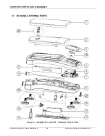
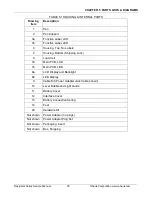
TABLE 5-1 HOUSING & INTERNAL PARTS 

Drawing 

Item 

Description 

Pan 

Pan Support 

3a 

Function Label, LCD 

3b 

Function Label, LED 

Housing, Top, No Labels 

Housing, Bottom (Shipping Lock) 

Load Cell  

7a 

Main PCB, LCD 

7b 

Main PCB, LED 

8a 

LCD Display and Backlight 

8b 

LED Display 

Cable Kit (Power Adapter Jack Cable shown) 

10 

Level Bubble and Light Guide 

11 

Battery Cover 

12 

Interface Cover 

13 

Battery Connection Spring 

14 

Feet 

20 

Hardware Kit 

Not shown 

Power Adapter (no plugs) 

Not shown 

Power Adapter Plug Set 

Not shown 

Packaging, Insert 

Not shown 

Box, Shipping 


Summary of Contents for Navigator NV1101

Page 1: ...SERVICE MANUAL Navigator Series Scales ...

Page 2: ......

Page 3: ...2 2 DIAGNOSTIC GUIDE 16 3 MAINTENANCE PROCEDURES 19 3 1 PREVENTIVE MAINTENANCE 19 3 2 OPENING THE SCALE 19 3 3 REPLACING THE LOAD CELL 21 3 4 REPLACING THE PRINTED CIRCUIT BOARD AND DISPLAY 23 3 5 REPLACING THE FUNCTION LABEL 23 3 6 DOWN STOP ADJUSTMENT 23 4 TESTING 25 4 1 TEST MASSES REQUIRED 25 4 2 OPERATIONAL TEST 26 4 3 SEGMENT DISPLAY TEST 26 4 4 LOAD CELL TEST USING RAMP 26 4 5 PERFORMANCE T...

Page 4: ...FACTOR GEO 40 B 6 FILTER SETTINGS 41 B 7 STABILITY SETTING 41 B 8 AUTO ZERO SETTING 41 B 9 EXPANDED RESOLUTION E PAnd 42 B 10RESET 42 B 11END 43 APPENDIX C SOFTWARE SERVICE TOOL INSTRUCTIONS 44 C 1 HARDWARE AND SOFTWARE SETUP 44 C 2 DEFINING LED DISPLAY VERSION 46 C 3 CONFIGURING THE SCALE 46 APPENDIX D GEOGRAPHICAL ADJUSTMENT VALUES 48 ...

Page 5: ...Geographical Adjustment Values 48 LIST OF ILLUSTRATIONS FIGURE NO TITLE 1 1 Power Connection 10 1 2 Navigator Overlay 10 1 3 Navigator Display Indicators 11 1 4 Menu Lock Switch 12 3 1 Pan Support and Conductive Rubber Caps 19 3 2 Separating the Top and Bottom Housings 19 3 3 Load Cell Connections 21 3 4 Position Load Cell PCB and AC Wires 21 3 5 Function Label Removal 22 3 6 Down Stop Adjustment ...

Page 6: ......

Page 7: ...ing a scale and after service Appendix B Service Calibration Describes the Service Menu and sub menus which allow authorized service personnel to perform factory Linearity and Span calibrations no pre set limits take Ramp readings adjust the GEO Factor and use E PAnd to temporarily increase readability to at least 1 10th of the standard readability Appendix C Software Service Tool Instructions Use...

Page 8: ...authority Before returning the scale to service an approved representative of the local Weights and Measures authority must certify the scale Ohaus does not generally recommend the repair of an approved scale that involves replacement of the load cell or PCB TABLE 1 1 SPECIFICATIONS NV non Approved Model NV212 NV511 NV1101 NV2101 NV4101 NV5101 Capacity g 210 510 1100 2100 4100 5100 Repeatability g...

Page 9: ...nsitivity 1 MPE 1 MPE NVL non Approved Model NVL511 NVL1101 NVL2101 NVL5101 NVL10000 NVL20000 Capacity g 510 1100 2100 5100 10000 20000 Repeatability g 0 2 0 2 0 2 1 2 2 Linearity g 0 2 0 2 0 2 1 2 2 OCL g 0 3 0 3 0 3 1 5 3 3 Zero Drift g C 0 2 0 2 0 3 1 2 2 Span Sensitivity d C 0 1 0 1 0 1 0 5 1 1 NVL CMC Approved Model NVL511B NVL1101B NVL2101B NVL5101B NVL10000B NVL20000B Capacity g 510 1100 21...

Page 10: ... 0 4 2 2 2 Linearity g 0 2 0 4 2 2 2 OCL g 1 MPE 1 MPE 1 MPE 1 MPE 1 MPE Zero Drift 1e 5 C 1e 5 C 1e 5 C 1e 5 C 1e 5 C Span Sensitivity 1 MPE 1 MPE 1 MPE 1 MPE 1 MPE NVT EC OIML Type Approved Model NVT1601M NVT3200M NVT6400M NVT16000M Capacity g 1600 3200 6400 16000 Repeatability g 0 5 1 2 5 Linearity g 0 5 1 2 5 OCL g 1 MPE 1 MPE 1 MPE 1 MPE Zero Drift 1e 5 C 1e 5 C 1e 5 C 1e 5 C Span Sensitivity...

Page 11: ...rac 7 x 17 x 38 x 74 x 144 x 179 x lb oz dec NA 1lb 1 99oz x 0 01oz 2lb 6 8oz x 0 01oz 4lb 10 07oz x 0 01oz 9lb 0 63oz x 0 01oz 11lb 3 9oz x 0 02oz lb oz frac NA 1lb 1 oz x oz 2lb 6 oz x oz 4lb 10oz x oz 9lb 0 oz x oz 11lb 3 oz x oz ozt 6 7515 x 0 0005 16 395 x 0 005 35 365 x 0 005 67 517 x 0 005 131 82 x 0 01 163 96 x 0 02 gr grn 3240 8 x 0 2 7870 x 2 16976 x 2 32408 x 2 63275 x 5 78700 x 10 N 2 ...

Page 12: ... x 0 05 NV Models EC OIML Type Approved Units NV311M NV3100M ct 2550 x 0 5 15500 x 5 g 311 x 0 1 3100 x 1 kg NA 3 1 x 0 001 NV Models NTEP MC Type Approved Units NV311N NV3100N ct 2550 x 0 5 15500 x 5 g 311 x 0 1 3100 x 1 kg NA 3 1 x 0 001 lb NA 6 835 x 0 005 oz 10 935 x 0 005 109 35 x 0 05 ozt 9 965 x 0 005 99 65 x 0 05 gr grn 4784 x 2 47840 x 20 dwt 199 3 x 0 1 1993 x 1 ...

Page 13: ... 0 74oz x 0 02oz 44lb 1 5oz x 0 05oz lb oz frac 1lb 1 oz x oz 2lb 6 oz x oz 4lb 10oz x oz 11lb 3 oz x oz 22lb 0 oz x oz 44lb 1 oz x oz ozt 16 395 x 0 005 35 365 x 0 005 67 517 x 0 005 163 96 x 0 02 321 50 x 0 02 643 x 0 05 gr grn 7870 x 2 16976 x 2 32408 x 2 78700 x 10 154320 x 10 308640 x 20 N 5 001 x 0 001 10 787 x 0 001 20 594 x 0 001 50 015 x 0 005 98 065 x 0 005 196 13 x 0 01 dwt 327 9 x 0 1 ...

Page 14: ... x 0 02oz 22lb 0oz x 0 02oz 32lb 0oz x 0 05oz lb oz frac 3lb 3 oz x oz 6lb 6 oz x oz 16lb 0oz x oz 22lb 0oz x oz 32lb 0oz x oz ozt 46 665 x 0 005 93 33 x 0 01 233 32 x 0 02 320 85 x 0 02 466 65 x 0 05 gr grn 22400 x 2 44800 x 5 112000 x 10 154000 x 10 22400 x 20 N 15 691 x 0 001 31 38 x 0 002 62 765 x 0 005 98 065 x 0 005 156 91 x 0 01 dwt 933 3 x 0 1 1866 6 x 0 2 4115 5 x 0 5 6417 x 0 5 9333 x 1 ...

Page 15: ... 6 4 x 0 002 16 x 0 005 NVT Models NTEP MC Type Approved Units NVT1601N NVT3200N NVT6400N NVT16000N ct 8000 x 5 16000 x 5 32000 x 10 80000 x 50 g 1600 x 0 5 3200 x 1 6400 x 2 16000 x 5 kg 1 6 x 0 0005 3 2 x 0 001 6 4 x 0 002 16 x 0 005 lb 3 2 x 0 001 6 4 x 0 002 16 x 0 005 32 x 0 01 oz 51 20 x 0 02 102 40 x 0 05 256 x 0 1 512 x 0 2 ozt 466 66 x 02 93 35 x 0 05 233 3 x 0 1 466 6 x 0 2 gr grn 22400 ...

Page 16: ...section contains information on the basic operation of the scale The included AC adapter may be used to power the scale when battery power is not available Figure 1 1 Power Connection 1 6 1 Overview of the Controls Figure 1 2 Navigator non approved models Overlay Figure 1 2 Navigator approved models Overlay Input Jack ...

Page 17: ...description Long Press Toggles through active units Short Press in Menu Toggles through available settings Function Mode Back Short Press Selects function setting Long Press Selects active Mode Short Press in Menu returns to previous settings Tare Menu Exit Short Press Enter clear a Tare value Long Press Enters User Menu Short Press in Menu Quickly exit User Menu IR Sensor Left IR Sensor Right IR ...

Page 18: ...ed value has become stable 2 Indicates that the indicated value is within the center of zero 3 Symbols for weighing units or modes 4 Arrows indicate the current operation mode of the IR Sensors 5 High Accept Low indicators for check weigh mode 1 6 3 Power On With power connected AC Adapter or battery press Zero After segment display OHAUS and software revision number the display will show 0 00 and...

Page 19: ...by the approval agency To gain access to these submenus see the next section 1 7 LEGAL FOR TRADE LFT When the scale is set for LFT on M and N models the following menu settings cannot be accessed changed Calibration Mode and Units The switch in type approved models may set some balance settings as required by the approval agency In non approved models the Menu lock switch will also limit access to...

Page 20: ...his message confirms the proper setting of the LFT mode and the hardware lock switch Verify proper scale operation and that the required legal requirements are met CAL is locked available modes and units are correct etc 9 The scale can now be sealed if the proper authority is present If the scale cannot be sealed at the current location then the customer must do so at his or her location before th...

Page 21: ... 1 GETTING STARTED Navigator Series Service Manual 15 Ohaus Corporation www ohaus com TABLE 1 6 NAVIGATOR SERVICE MENU STRUCTURE Service Menu Menu Items Ramp Lin Span Geo Filter Stability AZT Expand Reset End ...

Page 22: ...ction 3 6 3 Use the error code table for solutions for specific codes 4 Use the Diagnostic Guide locate the symptom then follow the suggested remedies in order 2 2 DIAGNOSTIC GUIDE Table 2 1 is a Diagnostic Guide designed to help locate the problem area quickly and easily The probable causes are listed with the most common cause first If the first remedy does not fix the problem proceed to the nex...

Page 23: ...inearity calibration Unstable environment vibration air currents or changing temperature Move scale to suitable location allow scale to stabilize its temperature Bad load cell Replace load cell Poor repeatability Internal mechanical interference Verify the pan Support is not contacting the top housing Check that the shipping lock is not touching the Pan Support Bad load cell Replace load cell Cann...

Page 24: ...in scale service menu to check Load Cell and then calibrate Load Cell is damaged Replace Load Cell Err 8 3 ˉLoadˉ Overload cap 9e Load exceeds balance maximum capacity remove weight from the pan Err 8 4 _Load_ Under load Reading below min range Re install pan Err 8 5 tArE Tare out of range 1 Switch to a unit where the tare Max 2 Clear the tare No load on the pan Press tare button 3 Clear the tare ...

Page 25: ... the scale using a damp cloth with warm water CAUTION DO NOT USE CHEMICAL CLEANERS OR SOLVENTS OF ANY TYPE SOME CLEANERS ARE ABRASIVE AND MAY AFFECT THE SCALE S FINISH 3 Check the Power Cord for broken or damaged insulation 4 If using batteries and the scale malfunctions first replace the batteries to see if this resolves the problem To isolate a problem with the rechargeable battery option kit th...

Page 26: ...Pan Support Conductive Rubber Caps 3 Remove the Pan Support by removing the two screws shown in Figure 3 1 4 Remove the 5 screws holding the Top and Bottom Housings in place See Figure 3 2 Note NV model shown Figure 3 2 Separating the Top and Bottom Housings 5 Turn the scale over and remove the upper housing Screws that secure the housings ...

Page 27: ...d directly to the PCB Before disconnecting the cable record the wire colors and their location on the PCB Hint A digital picture is an easy and reliable record Disconnect the cable connecting the PCB to the Load Cell by un soldering the 5 wires from the PCB Take care not to over heat the PCB which will damage the thin PCB conductors Re Assembly 1 Re solder the new load cell to the PCB connection J...

Page 28: ...rews so that the load cell can be aligned in the housing While holding the load cell fully tighten the screws The screws should be tight enough so that the load cell does not move when pushed from the side Verify that the load cell is centrally located between the ribs 3 Turn the scale over onto its feet Position the PCB on to its locating pins Coil the excess load cell cable in front of the load ...

Page 29: ... wires through their holes check that the new assembly is seated properly on the PCB and then solder the lead wires 3 5 REPLACING THE FUNCTION LABEL The Function Label may need to be replaced See Chapter 5 for parts information Use a broad blade such as a wide X Acto knife to remove the label Clean the glue residue from the Housing surface Then carefully place the new label where the old one was S...

Page 30: ...river Each adjustment screw should contact the Base when 120 to 150 of the scale capacity is placed in the center of the 4 quadrants of the scale The Top Housing must be removed to visually check if the down stops are touching Turn the adjustment screw counterclockwise to increase the clearance and clockwise to decrease the clearance An easy method to check the down stop adjustment is to use the s...

Page 31: ... scales must meet the requirements of ASTM Class 4 or OIML F2 Tolerance The mass values are listed in Table 4 1 TABLE 4 1 CALIBRATION MASS VALUES Model Span Calibration mass Linearity Calibration masses NV212 200g 100g 200g NV311 N or M 200g 200g 300g NV511 300g 300g 500g NV1101 500g 500g 1000g NV2101 1kg 1kg 2kg NV3100 N or M 2kg 2kg 3kg NV4101 2kg 2kg 4kg NV5101 3kg 3kg 5kg NVL511 300g 300g 500g...

Page 32: ... the required batteries 2 Plug the Power Cord into a suitable power source 4 3 SEGMENT DISPLAY TEST Turn the scale on and ensure that all segments are enabled and displayed briefly This is a Segment Display Test See Figure 4 1 and Figure 4 2 Figure 4 1 LCD Segment Display Figure 4 2 LED old Segment Display Figure 4 3 LED new Segment Display 4 4 LOAD CELL TEST USING RAMP To test the Load Cell using...

Page 33: ... 2 1 MPE NVT3201 1 2 2 3 NVT3200 N or M 1 1 2 1 MPE NVT6400 N or M 1 1 2 1 MPE NVT6401 1 2 2 3 NVT10001 1 2 2 3 NVT16000 1 2 2 3 NVT16000 N or M 1 1 2 1 MPE NOTE The following performance tests are used to evaluate scale operation before and after repairs The scale must meet the requirements specified in each test as well as the specifications listed in Table 4 2 Before proceeding with the followi...

Page 34: ... 5 2 Repeatability Test The repeatability specification is defined as the Standard Deviation value derived from a set of weight readings This test uses more weight data than the Precision Test and will allow for occasional weight deviations due to testing variations Requirements To perform this test a single mass must be used for all readings The test mass should be approximately of the capacity o...

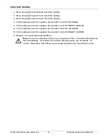
Page 35: ... Deviation Square Root of sum of Delta x Delta 9 5 Add the ten readings and divide the total by 10 to find the Mean average 6 Mean Reading 1 Reading 2 Reading 3 Reading 4 Reading 5 7 Reading 6 Reading 7 Reading 8 Reading 9 Reading 10 10 Mean ________ 6 Calculate the Delta for each reading and record in the work sheet Delta Reading Mean 7 Calculate the Delta x Delta for each reading and record in w...

Page 36: ...0g NV3100 N or M 750g 750g 1500g 2250g NVL5101 1250g 1250g 2500g 3750g NVL10000 2500g 2500g 5000g 7500g NVL20000 5000g 5000g 10000g 15000g NVT1601 400g 400g 800g 1200g NVT1601 N or M 400g 400g 800g 1200g NVT3201 750g 750g 1500g 2250g NVT3200 N or M 750g 750g 1500g 2250g NVT6400 N or M 1500g 1500g 3000g 4500g NVT6401 1500g 1500g 3000g 4500g NVT10001 2500g 2500g 5000g 7500g NVT16000 4000g 4000g 8000...

Page 37: ...ove the mass halfway between the center and the edge to the front of the Pan Note any differences in the displayed weight reading 9 Repeat the test for the back left and right position of the Pan 10 Maximum allowable change in displayed weight readings for each of the four positions can be found in Specifications Tables Chapter 1 If this maximum is exceeded follow procedures in Section 4 5 5 Adjus...

Page 38: ...If the reading at point B is negative file at points 1 and 2 STRAIGHT ACROSS 9 If the reading at point C is negative file at points 2 and 3 AT AN ANGLE 10 If the reading at point D is negative file at points 3 and 4 STRAIGHT ACROSS 11 Repeat 1 to 10 until within specifications Note It is not recommended that you try to adjust more than 5 counts if the beam has been filed already If the beam has no...

Page 39: ...cale in the field NOTE In all cases where a part is replaced the scale must be thoroughly checked after the replacement is made The scale MUST meet the parameters of all applicable specifications in this manual If further technical information is needed please contact your local Ohaus distributor or Ohaus Corporation www ohaus com 7 Campus Drive Suite 310 Parsippany NJ 07054 USA Tel 973 377 9000 F...

Page 40: ...CHAPTER 5 PARTS LISTS DIAGRAMS Ohaus Corporation www ohaus com 34 Navigator Series Service Manual 5 1 HOUSING INTERNAL PARTS Figure 5 1 Navigator NVL and NVT Housing Internal Parts ...

Page 41: ...4 Housing Top No Labels 5 Housing Bottom Shipping Lock 6 Load Cell 7a Main PCB LCD 7b Main PCB LED 8a LCD Display and Backlight 8b LED Display 9 Cable Kit Power Adapter Jack Cable shown 10 Level Bubble and Light Guide 11 Battery Cover 12 Interface Cover 13 Battery Connection Spring 14 Feet 20 Hardware Kit Not shown Power Adapter no plugs Not shown Power Adapter Plug Set Not shown Packaging Insert ...

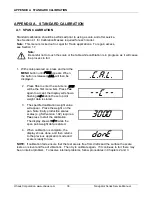
Page 42: ...l 2 Press Yes to enter the sub menu SPAN will be the first menu item Press Yes again to accept the display will show a flashing C while the zero point weight data is stored C 3 The specified calibration weight value will appear Place the weight on the pan Note Early production scales scales e g SW version 1 02 require a Yes press to start the calibration The display shows C while the span point we...

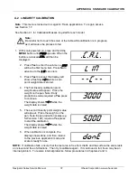
Page 43: ...hile a zero point weight data is stored C 4 The first linearity calibration point weight value will appear Place the weight on the pan Note Early production scales required a Yes press to continue The display shows C while the weight data is stored 3000 5 The second linearity point weight value will appear Place the weight on the pan Note Early production scales e g SW version 1 02 require a Yes p...

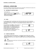
Page 44: ...le is increased The ramp display should remain constant without fluctuations If you press Yes to select Ramp a number appears It should be constant Add masses from minimum to maximum capacity The reading will increase but should not fluctuate The example at right is with no weight on the Pan It will vary with other scales 19 To exit the ramp function press Yes The scale advances to the Linear cali...

Page 45: ...nds and advances to SPAN Done Press Yes to confirm a span calibration SpaN B 4 SPAN CALIBRATION Span calibration from the service menu allows you to set a new zero and maximum setting This is distinct from user level span calibration which allows a user to adjust the zero and maximum setting within the range established by the service menu span setting Span calibration automatically follows linear...

Page 46: ...o accurately calibrate the scale at a location other than the location where the scale is to be used Prior to calibration the Geo Factor is set to correspond to the geographical location where the calibration is being performed Following calibration the Geo Factor is changed to match the location where the scale is to be used If required the scale may also be sealed according to the required appro...

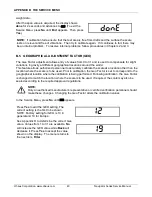
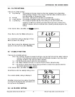
Page 47: ...setting menu FiLtEr The current filter setting is displayed Press No to increment the setting L2 Press Yes to accept the displayed value and advance to the next menu item Stability L3 B 7 STABILITY SETTING There are four stability settings 0 5d This is setting requires the weight reading to vary less than 0 5d for the stable indicator to be on This setting will require more time for the stable ind...

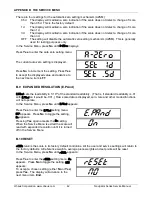
Page 48: ...he next menu item LFT Set 5d B 9 EXPANDED RESOLUTION E PAnd E PAnd sets the readability to 1 10th of the standard readability That is if standard readability is 01 with E PAnD on it would be 001 Raw scale data is displayed zero tare and other modes functions will not operate In the Service Menu press No until E PAnD appears Press Yes to enter the E PAnD setting menu OFF appears Press No to toggle ...

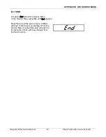
Page 49: ... B 11 END Accepting End will exit the Service Menu In the Service Menu press No until EnD appears Press Yes to exit the service menu or No to advance to the ramp menu setting When the Service Menu is exited the scale will return to the last active mode with any changes from the Service menu EnD ...

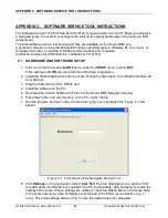
Page 50: ... this setting is left ON the scale will shut off during configuration 2 Install the RS232 Interface Kit into the scale Follow the instructions in the RS232 Interface Kit User Manual 3 Plug the cable into the PC s RS232 port 4 Install the software on the PC 5 Download the Service Software ZIP file from the Ohaus DMX Navigator directory 6 Place the Zip file in its own directory on the PC un Zip the ...

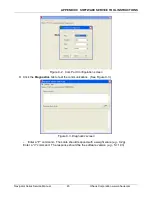
Page 51: ... www ohaus com Figure C 2 Com Port Configuration screen 9 Click the Diagnostics tab to test the communications See Figure C 3 Figure C 3 Diagnostic screen Enter a P command The scale should respond with a weight value e g 0 2g Enter a V command The response should be the software version e g Sr 1 03 ...

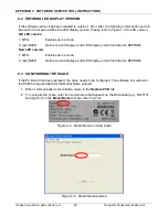
Page 52: ...y as old LED display store this data into EEPROM New LED version 1 MFG Enable service mode 2 esc NLED Define current display as old LED display store this data into EEPROM C 3 CONFIGURING THE SCALE If the PC Board has been replaced the scale needs to be configured The software tool will send the PCB the required data for the Model Name entered 1 When communications are reliable return to the Repla...

Page 53: ...aus Corporation www ohaus com 3 Click Start 4 The bar is a graphical measure of the configuration progress 5 When the downloading is complete turn the scale off 6 Turn the scale on and perform a Service Calibration see Appendix B followed by Operational and Performance tests Chapter 4 ...

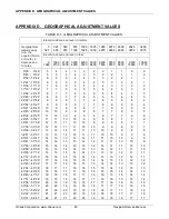
Page 54: ...31 54 41 05 05 06 06 07 07 08 08 09 09 10 10 11 11 12 12 13 13 14 14 15 15 16 16 17 17 18 18 19 19 20 20 21 21 22 04 05 05 06 06 07 07 08 08 09 09 10 10 11 11 12 12 13 13 14 14 15 15 16 16 17 17 18 18 19 19 20 20 21 21 04 04 05 05 06 06 07 07 08 08 09 09 10 10 11 11 12 12 13 13 14 14 15 15 16 16 17 17 18 18 19 19 20 20 21 03 04 04 05 05 06 06 07 07 08 08 09 09 10 10 11 11 12 12 13 13 14 14 15 15 1...

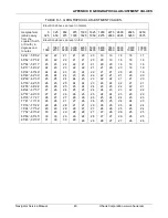
Page 55: ... 59 32 60 49 60 49 62 09 62 09 63 30 63 30 64 55 64 55 66 24 66 24 67 57 67 57 69 35 69 35 71 21 71 21 73 16 73 16 75 24 75 24 77 52 77 52 80 56 80 56 85 45 85 45 90 00 22 23 23 24 24 25 25 26 26 27 27 28 28 29 29 30 30 31 22 22 23 23 24 24 25 25 26 26 27 27 28 28 29 29 30 30 21 22 22 23 23 24 24 25 25 26 26 27 27 28 28 29 29 30 21 21 22 22 23 23 24 24 25 25 26 26 27 27 28 28 29 29 20 21 21 22 22 ...

Page 56: ......

Page 57: ......

Page 58: ...rporation all rights reserved Registered trademark of Ohaus Corporation The information contained in this manual is believed to be accurate at the time of publication but Ohaus Corporation assumes no liability arising from the use or misuse of this material Reproduction of this material is strictly prohibited Material in this manual is subject to change ...

Reviews: