


3-14
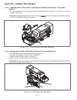
CHAPTER 3 REPAIR PROCEDURES
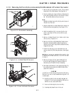
3.1.19
Monoblock Load Cell Removal from High Capacity Top Loader Balance
Refer to Figure 5-6 in Chapter 5 for location of components called out in this procedure and Figure 3-19. To remove the
Monoblock Load Cell, proceed as follows:
1.With the balance turned OFF and unplugged, remove the Pan (1).
2.Remove four Pan Mounts (2).
3.Remove four Cover Housing Screws (3) which secures the Housing Cover (4) to Base (19).
4.Loosen the four Screws (17) which secures the Overload Protection (18) from Base (19).
5.Carefully lift the Overload Protection up from the Weigh Assembly (20) and out of the Base (19).
6.Disconnect the Coil Cable Connector (8) and the Cell Cable Connector (9) from the Main PCB (6).
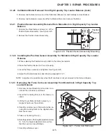
7.Remove the two Protective Plate Screws (5) holding the Main PCB (6) and Power Supply PCB (7).
8.Carefully lift both PC boards upwards and disconnect Connector PCB Cable (10) from the Power Supply PCB
(7).
9.Remove the Cable Guide (26) from inside of the Base (19).
10.Turn the Balance on it's side exposing the bottom and while holding the Weigh Assembly (20) inside of the
Base (19), then, remove the three Base Screws (12) from the Base (19).
11. Remove the Weigh Assembly (20) from the Base (19).
To remove the Monoblock (23) from the Weigh Assembly (20), continue as follows:
12. Loosen the four Hex Head Screws (22) (7.5 mm) on the Weigh Assembly (20). These screws secure the
Weigh Assembly to the Monoblock (23).
13. Loosen the four Screws (24) which secures the U-Block (25) to the Monoblock (23).
14. Remove the Monoblock (23).
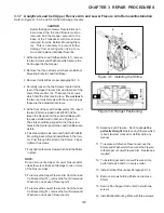
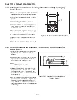
Figure 3-19. Calibration Motor Removal.
3.1.20
Calibration Motor Removal from High Capacity Top Loader Balance
Refer to Figure 5-6 in Chapter 5 for location of components called out in this procedure and Figure 3-19. To remove the
calibration motor, proceed as follows:
1.Perform procedure as described in paragraph
3.1.19 and remove the Monoblock (23) and PC
boards.
CAUTION
Remove Monoblock carefully so that the two calibra-
tion weight spindles are not subject to stress and never
touch anything during removal. Careless removal
could damage the calibration mechanism. Hold the
Monoblock only right at the front or the back by the
section fastening.
2.Remove two screws (6) which secure the
Calibration Weight Holders (1) both sides.
and remove Calibration Weights Holders
3.Remove two Calibration weights (2).
4 Remove the Motor Cable (38) (See Figure 5-
6) from Internal Calibration Motor Board (5).
Cable may have to be redressed behind PC
board when reassembling.
1
2
3
4
5
6
Summary of Contents for EXPLORER
Page 2: ......
Page 4: ......
Page 62: ...4 10 CHAPTER 4 TESTING ...
Page 88: ...5 26 CHAPTER 5 DRAWINGS AND PARTS LISTS ...
Page 106: ...APPENDIX B EXPLORER PRO EP LOADER B 10 ...
Page 112: ...APPENDIX D REPLACING BOTTOM DISPLAY BOARD D 4 ...
Page 113: ......
Page 114: ...PN 80250985 SERVICE MANUAL EXPLORER EXPLORER PRO AND VOYAGER BALANCES 80250985 ...


