


3-10
CHAPTER 3 REPAIR PROCEDURES
3.1.14
Installing the Position Sensor Assembly for Monoblock Precision Top Loader
Balance
3.1.15 Changing the Load Cell Board for Precision Top Loader Balance
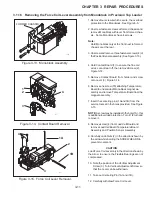
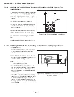
1.Unsolder Temperature Sensor board cable (1) (Figure 3-12).
2.Unsolder position Sensor Assembly from cell board (2).
3.Disconnect main PC board cable connector (3).
4.Remove Load Cell Board screw and change board.
CAUTION: When screwing in, first turn the self-tapping cell board screw in a counterclockwise direction until the first
screw thread engages and then tighten it.
210
1
2
3
Figure 3-12. Changing Load Cell Board.
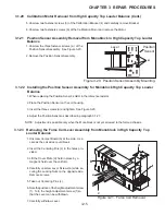
102
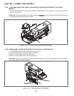
1
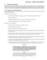
Figure 3-11. Position Sensor Assembly Mounting.
1.Mount Position Sensor Assembly, align centrally on the lateral stop pin (1), (Figure 3-11) of the lever and fasten
with the three screws.
Please note: The flange of the Position Sensor Assembly is prebent to ensure its precise positioning after screwing
on. Please do not attempt to bend it straight!
Summary of Contents for EXPLORER
Page 2: ......
Page 4: ......
Page 62: ...4 10 CHAPTER 4 TESTING ...
Page 88: ...5 26 CHAPTER 5 DRAWINGS AND PARTS LISTS ...
Page 106: ...APPENDIX B EXPLORER PRO EP LOADER B 10 ...
Page 112: ...APPENDIX D REPLACING BOTTOM DISPLAY BOARD D 4 ...
Page 113: ......
Page 114: ...PN 80250985 SERVICE MANUAL EXPLORER EXPLORER PRO AND VOYAGER BALANCES 80250985 ...


