


3-3
CHAPTER 3 REPAIR PROCEDURES
3.1.3 Analytical Load Cell Position Sensor Adjustment With Test Points
When the Analytical Load Cell Assembly (9) has been repaired either an Upper or lower Flexure Arm Assembly or Vertical
Flexure has been replaced, it may be necessary to adjust the Position Sensor. Refer to Figures 3-1, 5-3 and 5-4.
1.Remove the Analytical Load Cell from the balance, see paragraph 3.1.1.
2.Plug the Position Sensor PCB Assembly Cable into the Main PC Board (11). DO NOT CONNECT THE
LOAD CELL CABLE.
3.Apply power to the balance.
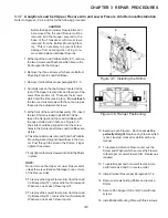
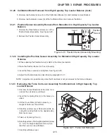
4.Refer to Figure 3-1 and using a Digital Voltmeter set to measure dc voltage, connect the (DVM) to the two
terminal contacts located on the right hand side of the Sensor Board (51C) (See Figure 5-4) as follows:
Black or ground test lead to the negative terminal on the Sensor PC Board.
Red or positive test lead to the positive terminal on the Sensor PC Board.
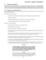
+ -
ADJUSTMENT SCREWS
SENSOR PC BOARD
PRECISION RESISTOR
CONNECTIONS
SENSOR CABLE
CONNECTIONS
Figure 3-1. Analytical Sensor Board Adjustment Locations and Connections.
5.Push down on the Pan Support which is located on top of the Transducer (brass fitting), the reading on
the DVM will be approxi2.xxx volts dc.
6.Pull up on the Pan Support, the reading on the DVM will be approximately 2.xxx volts dc.
7.Adjust up stop for equal swing between readings in steps 5 and 6. See Figure 5-4 for location of stop screw.
8.Reassemble the balance, follow the procedure in paragraph 3.1.2.
Summary of Contents for EXPLORER
Page 2: ......
Page 4: ......
Page 62: ...4 10 CHAPTER 4 TESTING ...
Page 88: ...5 26 CHAPTER 5 DRAWINGS AND PARTS LISTS ...
Page 106: ...APPENDIX B EXPLORER PRO EP LOADER B 10 ...
Page 112: ...APPENDIX D REPLACING BOTTOM DISPLAY BOARD D 4 ...
Page 113: ......
Page 114: ...PN 80250985 SERVICE MANUAL EXPLORER EXPLORER PRO AND VOYAGER BALANCES 80250985 ...