background image

Ogden Metalworks, Inc. — 217-582-2552 

30 

  Hay Runner™ Hay Rake

9.  Maintenance

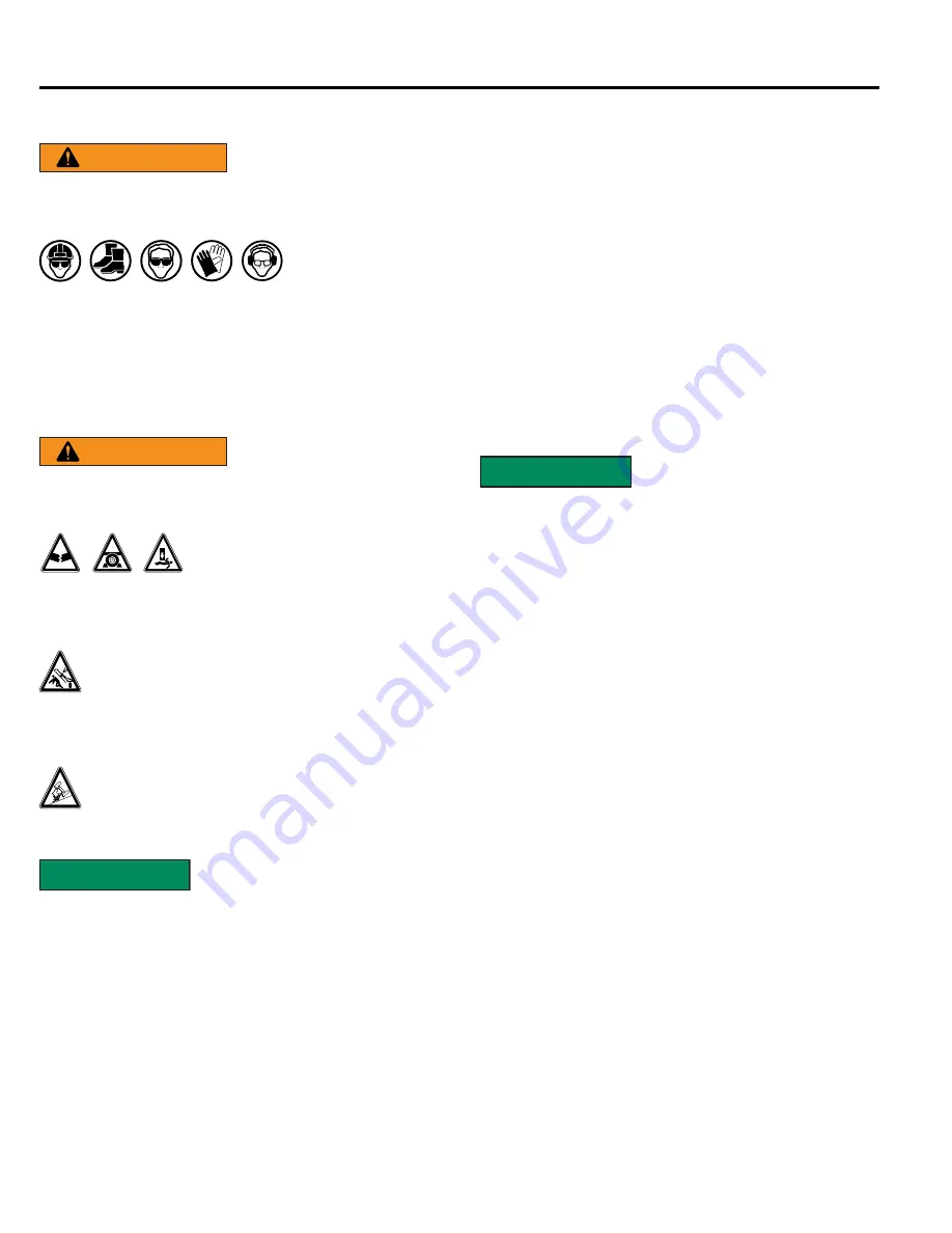
9.1  General Maintenance Safety

WARNING

Failure to comply with 

the following safety 

instructions could result in serious injury and 

possibly even death.


Personal  

Protection  

Equipment  

Wear personal protection equipment (PPE), 

which may include hard hat, safety glasses, 

safety shoes, gloves, etc. appropriate for the 

work site and working conditions.

9.2  Work Area

WARNING

Failure to comply with 

the following safety 

instructions could result in serious injury and 

possibly even death.


Crush Hazard


Always set the wheel rake on 

safety stands or on the 

ground and chock the wheels when performing 

maintenance. 

Crush hazard


The rake arms can drop unexpectedly if 

the wing locks are not installed. Whenever 

the wings are raised the transport locks, and 

their retaining pins must be installed.

The wheel rake is top heavy when the 

wings are raised.  Make sure the rake is on 

a firm, level surface before performing any 

maintenance.

SAFETY

INSTRUCTIONS

The following safety 

instructions are provided to 

help prevent injury or limit equipment damage. 
A fire extinguisher and first aid kit should be 

readily accessible while performing maintenance 

on this equipment.
Do not leave tools lying around the work area.  

Follow good shop practices.  Keep service area 

clean and dry.  Be sure electrical outlets and 

tools are properly grounded.  Use adequate light.
Keep all parts in good condition and properly 

installed. Fix damage immediately. Replace worn 

or broken parts. 

Use the correct tools, jacks, hoists, or other 

tools that have the capacity for the job.
Use certified safety stands rated to support the 

wheel rake’s weight when working beneath the 

wheel rake.
Do not position jack stands under moveable 

parts. Test the stability of the wheel rake before 

working underneath.
If the wheel rake is attached to the tractor, set 

the brakes, remove the key, chock the tractor 

wheels, and block the wheel rake before working 

underneath.

9.3  Parts Replacement

SAFETY

INSTRUCTIONS

Replacement parts must be 

genuine factory replacement 

parts to restore the unit to its original 

specifications. The manufacturer will not accept 

responsibility for damages as a result of using 

unapproved parts.
Replace any worn, cut, abraded, flattened, or 

crimped hoses.

Summary of Contents for RCR812

Page 1: ...Owner s Manual Read Understand and Follow the information and procedures in this manual to safely operate and maintain the Hay Runner wheel rake For Hay Rakes after serial 01425 ...

Page 2: ......

Page 3: ...4 7 Hay Rake Wheels 17 4 8 Adjust Height of Hitch 17 4 9 Grease the Pivot Pins 17 4 10 Optional Center Wheel Kit 18 5 INITIAL SET UP 20 5 1 Setting Up the Wheel Rake 20 5 2 Attaching to Tractor 20 5 3 Purge Air from Hydraulic Lines and Cylinders 20 5 4 Level the Rake 21 5 5 Wing Extension Adjustment 21 5 6 Rake Angle Adjustment rear center rake wheels 22 5 7 Rake Angle Adjustment front center rake...

Page 4: ...twelve wheels with an optional set of front mounted kicker wheels to turn the center of the windrow 1 3 Safe Operation Safe efficient and trouble free operation of your wheel rake requires that you and anyone else who will be using or maintaining the unit read and understand the information contained within this manual and other related OEM equipment manuals Store this manual in the Manual Caniste...

Page 5: ...onditions Dimensions vary per model 1 5 Intended Usage Do not use this wheel rake for any other purpose than its intended use of raking hay and other forage crops If the wheel rake is used or altered in any way from the original design the manufacturer does not accept any liability for injury or warranty 1 6 Operator Orientation The directions left right front and rear as mentioned throughout this...

Page 6: ..._ Purchase Date _____________________________ Dealer ____________________________________ Address __________________________________ __________________________________ Phone Number _____________________________ 1 10 Owner Operator Manual Storage Store the Operator manual and other operating materials in the document storage tube located on the tongue 1 11 Unanswered Questions If you have any quest...

Page 7: ...ld also ensure that the unit will not be damaged or be made unsafe by the methods that you choose The information specifications and illustrations in this manual are based on the information that was available at the time this material was written and can change at any time 2 2 Safety Alert Symbol This is the safety alert symbol It is used to alert you to potential personal injury hazards Obey all...

Page 8: ...ment Do not weld Use proper tools N ING AR Warning decal alert Stop machine engine Check Maintain Fluid Levels Place in neutral Remove key STOP Stop engine Set parking brake 2 3 2 Prohibited Actions No riders No children 2 3 3 Hazard Avoidance Safety alert symbol Crushing hazard Crushing hazard Falling hazard Fire hazard Hot surface Sharp object hazard High pressure fluid hazard 0 Zero pressure En...

Page 9: ...2 10 OSHA Training Requirements on page 8 Stay Clear Clear the area of people especially small children before using the wheel rake Under no circumstances should young children be allowed to work with or around the wheel rake Crush Hazard Hydraulic or mechanical failure can allow a wing to drop suddenly without warning Do not allow anyone to walk under or stand near a raised rake arm Impaired User...

Page 10: ...s in other sections should also be followed 2 6 Transporting Safety Refer to 2 6 Transporting Safety on page 8 for safety recommendations related to transporting the wheel rake All applicable safety recommendations in other sections should also be followed 2 7 Storage Safety Refer to 2 7 Storage Safety on page 8 for safety recommendations related to storing the wheel rake All applicable safety rec...

Page 11: ... is or will be involved These will include but are not limited to instructions to Keep all guards in place when the machine is in operation Permit no riders on equipment Stop engine disconnect the power source and wait for all machine movement to stop before servicing adjusting cleaning or unclogging the equipment except where the machine must be running to be properly serviced or maintained in wh...

Page 12: ... clean the wheel rake avoid spraying too close to decals high pressure water can enter through very small scratches or under edges of decals causing them to peel or come off 4 Locations for the labels and replacement part numbers are shown in this section 5 Replacement parts must have replacement labels attached during installation and or before the wheel rake is used 6 Labels are available from y...

Page 13: ... Locations Item Part Number Description Qty 1 HR169 Decal Warning Operating 1 2 HR170 Decal Overhead Hazard 2 3 0 70 Decal Caution Stay Clear 5 4 HR171 Decal Warning Pinch Point 2 5 0 82 Decal Hydraulic Caution 1 6 0 71 Decal Red Reflector 2 7 B489A Decal Yellow Reflector 2 ...

Page 14: ...Ogden Metalworks Inc 217 582 2552 12 Hay Runner Hay Rake 3 4 1 Wheel Rake Safety Signs 1 2 3 4 ...

Page 15: ...Hay Runner Hay Rake 13 Ogden Metalworks Inc 217 582 2552 5 6 ...

Page 16: ...formation refer to 4 4 Attach the Tongue Assembly on page 15 5 Connect hydraulic supply and return hoses 6 Release the transport lock on both rake arms For detailed information refer to 4 5 Rake Arm Transport Locks on page 16 7 Lower the rake arms and if necessary attach the single or double rake wheel extension For detailed information refer to 4 6 Attach Optional Single or Double Wheel Extension...

Page 17: ...ts connecting the tongue to either the main frame or the tongue extension Place the tongue away from the work area CAUTION The tongue weighs approximately 96 pounds and may cause crushing injuries if not handled properly 9 If removing the tongue extension securely attach a lifting strap to the tongue extension Position the strap to balance the weight of the tongue as it is removed Remove the six 5...

Page 18: ...e make sure the transport locks are unlocked and pinned in the unlocked position NOTICE If the transport locks are not unlocked and the wheel rake arms are lowered the locks are designed to break away if enough pressure is applied If the locks are damaged in any way do not use the wheel rake Repair any damage before continuing to use the wheel rake 2 Place the lock pin through the transport lock a...

Page 19: ...ing bolts and adjust the hitch to the desired height 2 Reinstall both mounting bolts and tighten the hardware CAUTION Use only OEM supplied hardware to mount the hitch to the hay rake frame Use of a lesser grade bolt could result in failure of the hitch causing property damage or personal injury 4 9 Grease the Pivot Pins Once the unit is assembled grease the following three pivot point locations I...

Page 20: ...the weld on the tongue extension but stays straight perpendicular to the plate Tighten the four nuts 4 Install left hand rake arm 8 in the front ears of the mount plate and right hand rake arm 10 in the back ears using pivot pin 2 flat washer 3 and a cotter pin 4 Note Insert pivots pins 2 from the rake wheel side with the two bent ears facing up and sliding around the ear of the mount plate 5 Loos...

Page 21: ...r s rear port and then into the t fitting in the system s return hose 12 Attach the two rake wheels with six hex flange nuts 15 each Note Install the rake wheel labeled LH left hand on the right side and the rake wheel labeled RH right hand on the left side This orientation is opposite from the main rake wheels ...

Page 22: ...awbar and wheel rake hitch 1 Use the jack to adjust the hitch to the height of the tractor drawbar 2 Back the tractor up to align the drawbar and hitch pin holes CAUTION Do not stand or allow anyone else to stand between the tractor and the wheel rake while the tractor is moving or the engine is running 3 Turn off the tractor engine set the parking brake and dismount 4 Insert a 1 hitch pin with re...

Page 23: ... mount the hitch to the hay rake frame Use of a lesser grade bolt could result in failure of the hitch causing property damage or personal injury 5 Attach the wheel rake to the tractor following the procedure in 2 Purge all trapped air from the hydraulic lines and cylinders For detailed information refer to 5 3 Purge Air from Hydraulic Lines and Cylinders on page on page 20 6 Recheck the main fram...

Page 24: ...apply the parking brake before making this adjustment DO not place any part of your body under the wing of the rake SAFETY INSTRUCTIONS As an added precaution support the wing in the raised position to prevent it from lowering to the ground while the adjustments are made 2 Loosen the threaded tear shaped lock tab 3 Pivot the rake arm to the desired angle using the turnbuckle 4 Retighten the thread...

Page 25: ...the desired raking action without damaging the crop Excessive rake wheel ground pressure can cause crop damage premature rake wheel tine wear and broken tines 1 Adjust the spring pressure by loosening or tightening the eye bolt 2 Tightening the eyebolt decreases the ground pressure This work well with lighter hay Minimum Ground Pressure 3 Loosening the eyebolt increases the ground pressure This wo...

Page 26: ...akes 3 Relieve hydraulic fluid pressure 4 If parking the unit make sure jack stand is lowered and retaining pin is installed Crush Hazard The weight of the tractor plus the wheel rake if it rolls onto a person could cause serious crushing injury or death Crush Hazard The tractor should be equipped with a Roll Over Protective Structure ROPS and a seat belt A crushing hazard could occur if the drive...

Page 27: ...owed hay rake in the opposite direction of the mower s travel 5 Most raking problems can be traced to incorrect speed incorrect ground pressure or broken or missing tines 6 Use only enough ground pressure to pick up the crop material NOTICE Raise the rake wheels before backing the tractor Backing the tractor with the tines in contact with the ground will cause tine breakage 6 3 1 Raising Front Whe...

Page 28: ... Single Sided Rake Operation 1 Release the transport lock on the side being lowered to the ground The other side should be locked in place 2 Open rake arm lift cylinder valve The open position is when the valve handle is in line with the valve body 3 Close the lift cylinder valve on the rake arm which is not being lowered The closed position is when the valve handle is in perpendicular with the va...

Page 29: ...xiting the tractor 3 Remove the jack from the main frame and secure it to the hitch by fully inserting the locking pin through the jack and the hitch bracket Use the jack to raise the rake hitch to the height needed to disconnect the clevis from the drawbar 4 Disconnect the hydraulic hoses from the tractor Secure the hoses up off the ground CAUTION Make sure all hydraulic pressure is relieved befo...

Page 30: ...transporting the wheel rake on public roads SAFETY INSTRUCTIONS The following safety instructions are provided to help prevent injury or limit equipment damage Be a safe and courteous driver Anticipate road conditions and drive accordingly Apply brakes early Extra distance is required to stop the tractor and wheel rake Use care around unmovable objects that prevent clear vision of the complete wor...

Page 31: ...ding 1 Remove all entangled vegetation 2 Thoroughly wash the wheel rake to remove all clippings dirt mud or debris 3 Raise the rake arms and install the wing locks and their retaining pins 4 Store the wheel rake in an area that is dry level and free of debris inside a building is ideal SAFETY INSTRUCTIONS Store the wheel rake in an area away from human activity Do not permit children to play on or...

Page 32: ...ons are provided to help prevent injury or limit equipment damage A fire extinguisher and first aid kit should be readily accessible while performing maintenance on this equipment Do not leave tools lying around the work area Follow good shop practices Keep service area clean and dry Be sure electrical outlets and tools are properly grounded Use adequate light Keep all parts in good condition and ...

Page 33: ...airs Before performing any type of welding repair to the wheel rake contact Ogden Metalworks for approval Repair welding must be done with care and with procedures that may be beyond the capabilities of the ordinary welder WARNING Poorly done repairs or modifications to the wheel rake can result in serious injury or death should these repairs fail NOTICE Anyone performing a welding repair should b...

Page 34: ...ve the nuts from the tine retaining bolts 2 Remove the retaining bolts and the tine clamps 3 Reinstall the tines as shown The tine clamp is shown removed for clarity of the assembled tines around the retaining bolt Lubrication 1 Grease the flotation rods on a dual axle wheel spindle every 15 hours of operation 2 Lubricate the dual spindle axle seasonally ...

Page 35: ...pection 1 Periodically check the spindle retaining bolt to make sure it is tight 2 Check the hydraulic hoses periodically for cracks abrasions or leaks Replace defective hoses immediately with factory replacement parts only 3 Check tightness of lug bolts after one hour of operation and every six months thereafter Check tire pressure whenever maintenance is performed ...

Page 36: ...sion that will be released when the spring block is removed CAUTION Keep hands and fingers away from the spring 4 Install the new spring as shown 5 Place the end of the spring into the spring block and install the spring block onto the shaft Note The spring block must be rotated upward adding spring tension to align the keyway with the key in the shaft 6 Tap the spring block onto the shaft and tig...

Page 37: ...art unless otherwise noted Check tightness of bolts periodically using the bolt torque chart as a guide Always replace hardware with the same Grade bolt Standard Torque Values Bolt Diameter English Bolt Torque Specifications Grade 2 No Marking Grade 2 Grade 5 Grade 5 3 Radial Lines Grade 8 Grade 8 6 Radial Lines N m ft lbs N m ft lbs N m ft lbs 1 4 8 6 12 9 17 12 5 16 13 10 25 19 36 27 3 8 27 20 4...

Page 38: ...sively Too little ground pressure Increase the ground pressure Refer to 5 8 Adjust Rake Wheel Ground Pressure on page 23 Rake is missing hay Wheels running too fast Adjust rake arm angle Refer to 5 6 Rake Angle Adjustment rear center rake wheels on page 22 Tines missing or worn Replace tines It is best to replace all tines at the same time to keep a uniform height Bent tines Backing up with tines ...

Page 39: ...or become damaged our knowledgeable staff can make sure you receive the part s to put your unit back into operation Contact Information For replacement decals questions or to order parts contact your local dealer distributor If a local dealer cannot be found contract Ogden Metalworks Ogden Metalworks Inc PO Box 128 301 N Marilyn Avenue Ogden IL 61859 PH 217 582 2552 Fax 217 582 2746 www ogdenmetal...

Page 40: ...Ogden Metalworks Inc 217 582 2552 38 Hay Runner Hay Rake 11 2 Wheel Rake Frame ...

Page 41: ...14 Bumper Plate 2 28 RCR20R Wing Weldment Right 1 29 H34 4 534UB U Bolt 3 4 x 4 x 5 3 4 6 Item Part Number Description Qty 30 TB22507 Turnbuckle 2 31 CR31 Bushing 1 x 9 16 6 32 VM 604 Flange Bushing 1 1 4 x 1 1 4 4 33 RCR33 Pivot Pin Weldment 2 34 K 334 Hex Capscrew 1 4 x 1 2 35 RCR35L Lift Arm Weldment Left 1 36 RCR35R Lift Arm Weldment Right 1 37 K 335 Lockwasher 1 4 2 38 K 336 Hex Nut 1 4 2 39 ...

Page 42: ...gle Rake Arm Extension LH 1 5 HR224 Clip Front Wheel 2 4 6 HR221 HR222 2 Wh Rake Arm Extension RH 2 Wh Rake Arm Extension LH 1 8 HRB125 Bushing 9 VM 605 Grease Zerk 1 4 10 OE 154 Hex Nut 5 8 Item Part Number Description Qty 11 OE 155 Lockwasher 5 8 12 HRH12150 8 Hex Capscrew 1 2 x 1 1 2 GR8 13 0 161 Nylock Nut 1 2 14 21992 Wirelock Pin 3 8 15 HRH58SF SAE Flatwasher 5 8 16 HRH586 Hex Capscrew 5 8 x...

Page 43: ...0 Wheel 7 HR125 Tine Clamp 8 RP000369 Carriage Bolt M10 x 25 9 909176 Hub Cap 10 953005 Hex Castle Nut 1 14 11 909454 Cotter Pin 15 x 1 5 12 910253 Bearing Cone L44649 13 910250 Bearing Cup L44610 14 3819 Stud 3 8 Item Part Number Description Qty 15 105026C Hub Complete 16 906282 Seal 17 HR150 Rake arm with welded in spindle hub 18 VM 719 Machine Washer 1 1 4 18 ga 19 VM 609 Eye Bolt 3 8 x 3 1 2 2...

Page 44: ...Ogden Metalworks Inc 217 582 2552 42 Hay Runner Hay Rake 11 5 Single and Tandem Axles ...

Page 45: ...n Qty 1 HR117 Tire 4 2 HR133 Wheel 4 3 909900 Dust Cap 4 4 905936 Cotter Pin 4 Item Part Number Description Qty 5 953005 Castle Nut 4 6 951801 Flat Washer 4 7 910253 Outer Cone 4 8 910250 Outer Cup 4 9 912919 Wheel Nut 1 2 20 4 10 280090 Hub Complete 4 11 910251 Inner Cup 4 12 910252 Inner Cone 4 13 286929L14 Spindle 4 14 906281 Grease Seal 4 15 RCR15 Axle Weldment 2 16 HRB175 150 Bushing 1 3 4 x ...

Page 46: ... 1 8 662401 649206 Cylinder 3 x 12 SAE8 Seal Kit 2 10 CR202 Hose 3 8 x 20 8MJX 8MP 2 11 8MB 8MP90 Elbow 90 2 12 CR203 Hose 3 8 x 25 8MJX 8MB 2 13 CP316 214 Cotter Pin 3 16 x 2 4 14 8FJ CAP Cap 2 16 8MJ TEE Tee 3 18 HC V CB20 Flow Divider 1 19 FW14 Flatwasher 1 4 2 20 HRH140 Nylock Hex Nut 1 4 2 21 HRH143 Hex Capscrew 1 4 x 3 2 25 CR205 Hose 3 8 x 20 8MJX 8MB 1 Item Part Number Description Qty 27 8...

Page 47: ... HR123 Hex Flange Nut 3 8 12 17 HR124 Flange 2 18 912576 Washer 2 19 953005 Hex Castle Nut 1 2 20 909454 Cotter Pin 15 x 1 5 2 21 909176 Hub Ca 2 Item Part Number Description Qty 22 HR118 HR119 Rake Wheel Complete RH Rake Wheel Complete LH 1 1 23 HR121 Rake Tine 7mm 80 24 HR125 Tine Clamp 10 25 RP000369 Carriage Bolt M10 x 25 20 26 HR122 Hex Nut M10 20 27 W200060 S PMCK W200000 Cylinder 2 x 6 SAE6...

Page 48: ...f their manufacturer s warranties This warranty does not cover under any circumstances any parts components or materials which have been subjected to neglect misuse alteration accident or if repaired with parts other than those manufactured by and obtained from Ogden Metalworks Inc Credit for required labor will be issued at the company s discretion This warranty is extended solely to the original...

Page 49: ...Hay Runner Hay Rake 47 Ogden Metalworks Inc 217 582 2552 NOTES ...

Page 50: ...Ogden Metalworks Inc 217 582 2552 48 Hay Runner Hay Rake NOTES ...

Page 51: ......

Page 52: ...Manufactured by Ogden Metalworks Inc PO Box 128 301 N Marilyn Avenue Ogden IL 61859 PH 217 582 2552 Fax 217 582 2746 www ogdenmetalworks com ...

Reviews: