


Officine Gullo
20
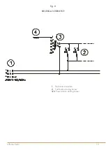
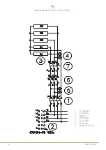
ELECTRIC CONNECTION
The appliance is supplied without the connection cable; to install it, proceed in the following way:
- Remove the back panel
- Push the connection cable through the cable channel, connect the conductor wires to the corresponding terminals
in the junction box and fix them into place.
- Block the cable with the cable blocker, and reassemble the panel. The earth wire must be longer than the others so
that if the cable blocker should break, it will disconnect after the tension wires.
N.B. The connection cable must have the following characteristics: it must be type H05RN-F and must have an
adequate section for the power of the appliance (see technical data table).
EQUIPOTENTIAL
The appliance must be connected to an equipotential system.
The connection screw is positioned at the back of the appliance and is identified by the symbol
.
Attention!
The manufacturer will neither be held responsible for, nor will give any compensation during the guarantee
period for any damage caused, and which is due to inadequate installations not compliant with the instructions.
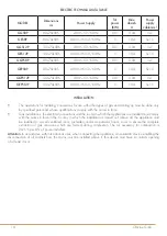
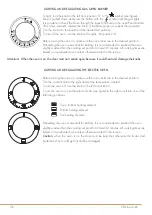
CHECKING HEAT OUTPUT
The appliances must be checked in such a way as to verify that the heat output is correct:
•
The heat output (thermal power) is indicated on the data plate of the appliance;
•
Firstly, check that the appliance can be used with the type of gas supplied; then check that the indication
on the plate corresponds to the gas to be used. For converting to another type of gas, check that the type
of gas complies with what is stated in this instruction manual.
The pressure is read with a gauge (minimum resolution of 0.1 mbar) inserted in the relative pressure outlet.
Remove the hermetically closed screw and insert the gauge pipe.
After reading, put back the screw tightening it hermetically and check for pressure leaks.
Connection for liquid gas G30/G31
The connection pressure for liquid gas is 30 mbar with butane and 37 mbar with propane.
Check the plate, read the pressure and verify that the description of the nozzle installed corresponds to the one
supplied by the manufacturer.
Connection with natural gas H G20
The connection pressure for natural gas is 20 mbar.
Check the plate, read the pressure and verify that the description of the nozzle installed corresponds to the one
supplied by the manufacturer.
21
Officine Gullo
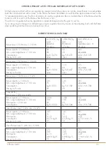
CHECKING PRIMARY AIR TO THE MAIN BURNERS AND PILOT NOZZLES
All the burners are fitted with an air regulator by means of which the primary air can be varied thanks to an adjustable
bush that can be locked with a screw. In the Burner Technical Data table you will find the approximate values for the
“h” parameter (primary air). The flow of primary air must be regulated so there is no detachment of the flame when the
burner is cold or a return of the flame when the burner is hot.
The pilot air is regulated when the appliance is tested and inspected for the gas it is set for.
If you are going to change to a different type of gas, regulate the air by means of the adjusting bush until the flame
stops sputtering and becomes an intense blue colour.
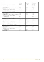
BURNER TECHNICAL DATA TABLE
Burner max 3,5 kW- min. 1,15 kW
12,8 kWh/kg
G30
BUTANE
30 mbar
12,8kWh/kg
G31
PROPANE
37 mbar
9,45 kWh/m
3
st.
G20
NATURAL GAS H
20 mbar
Burner injector 1/100 mm
Min. output adjustment 1/100 mm
Consumption
Primary air h=mm
90
50
kg/h 0,276
open
90
50
kg/h 0,272
open
145
adjustable
m3 st./h 0,370
open
Burner max 5,5 kW- min. 1,55 kW
Burner injector 1/100 mm
Min. output adjustment 1/100 mm
Consumption
Primary air h=mm
115
60
kg/h 0,434
open
115
60
kg/h 0,427
open
175
adjustable
m3 st./h 0,582
20
Burner max 7,5 kW- min. 2,5 kW
Burner injector 1/100 mm
Min. output adjustment 1/100 mm
Consumption
Primary air h=mm
135
75
kg/h 0,591
20
135
75
kg/h 0,582
20
205
adjustable
m3 st./h 0,794
20
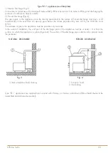
Coup de feu
Burner max 7 kW- min. 4 kW
Burner injector 1/100 mm
Min. output adjustment 1/100 mm
Pilot Injector 1/100 mm
Consumption
130A
100
20
kg/h 0,552
130A
100
20
kg/h 0,544
195
adjustable
35
m3 st./h 0,740
Oven Burner max 7,3 kW- min. 2,2 kW
Burner injector 1/100 mm
Min. output adjustment 1/100 mm
Pilot Injector
Consumption
Primary air h=mm
145
75
1x19
0.570 kg/h
12
145
75
1x19
0.570 kg/h
12
205
adjustable
1x27
0.772 m3 st./h
12
Oven Burner max 11 kW- min. 3,5 kW
Burner injector 1/100 mm
Min. output adjustment 1/100 mm
Pilot Injector
Consumption
Primary air h=mm
175
100
1x19
0.859 kg/h
13
175
100
1x19
0.859 kg/h
13
270
adjustable
1x27
1.164 m3 st./h
13
Summary of Contents for GGS8P
Page 2: ......
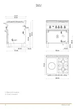
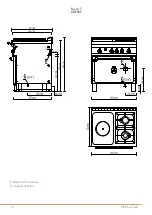
Page 4: ...Officine Gullo 4 E Electrical Connection G Gas Connection INSTALLATION MANUAL Fig A 1 GES8P ...
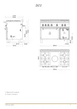
Page 5: ...5 Officine Gullo E Electrical Connection G Gas Connection Fig A 2 GES12P ...
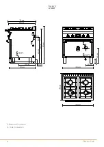
Page 6: ...Officine Gullo 6 E Electrical Connection G Gas Connection Fig A 3 GEPS8P ...
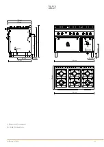
Page 7: ...7 Officine Gullo E Electrical Connection G Gas Connection Fig A 4 GEPS12P ...
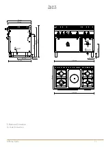
Page 8: ...Officine Gullo 8 E Electrical Connection G Gas Connection Fig A 5 GGS8P ...
Page 9: ...9 Officine Gullo E Electrical Connection G Gas Connection Fig A 6 GGS12P ...
Page 10: ...Officine Gullo 10 E Electrical Connection G Gas Connection Fig A 7 GGPS8P ...
Page 11: ...11 Officine Gullo E Electrical Connection G Gas Connection Fig A 8 GGPS12P ...
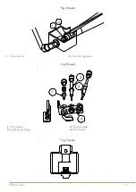
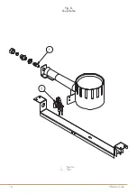
Page 14: ...Officine Gullo 14 Fig G Coup de feu 1 Injector 2 Pilot ...
Page 30: ...Officine Gullo 30 ...
Page 31: ...31 Officine Gullo ...