86
1
2
3
4
5
6
7
8
9
10
11
12
13
14
15
16
17
18
19
K
C – P
–
0 0
1
2
3
4
G
4
G
8
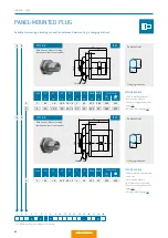
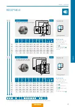
TECHNICAL DATA
•
IP 68 in mated condition.
•
Anti-rotation feature.
•
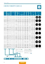
Contact con
fi
guration from
page 90.
•
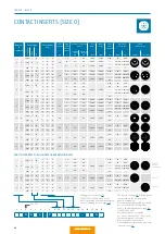
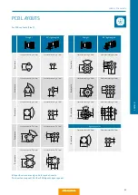
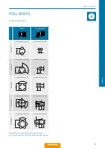
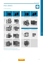
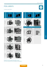
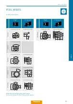
PCB layouts, see page 91.
•
Only straight PCB contact
possible.
1
2
Size
L1
1
mm
L2
mm
L3
2
mm
M
mm
D
mm
SW A
mm
SW B
mm
SW C
mm
C
mm
Panel cut-out
SW
mm
∅
mm
1
≈ 28
≈ 1.5 20.5 16 × 1
20
19
14.5
17
15.5 14.6 16.1
2
≈ 31
≈ 2
23
20 × 1
25
24
18.5
20
17
18.6 20.1
Installation from front of panel
with low installation depth
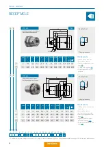
TECHNICAL DATA
•
IP 68 in mated and unmated
condition.
•
Anti-rotation feature.
•
No crimp contact possible.
•
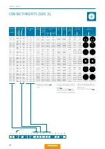
Contact con
fi
guration from
page 90.
•
Right-angled PCB contact
possible, see page 106.
•
Note: assembly wrench, see
page 158.
Size
L1
1
mm
L2
mm
L3
2
mm
M
mm
D 1
mm
D 2
mm
SW A
mm
C
mm
Panel cut-out
SW
mm
∅
mm
1
≈ 32
≈ 6
26.6 16 × 1
20
20
14.5
3.5
14.6
16.1
2
≈ 34
≈ 6
27
20 × 1
25
25
18.5
3.5
18.6
20.1
3
4
≈ 39
≈ 7
32.7 24 × 1
30
31
22.5
4.5
22.6
24.1
4
≈ 42
≈ 6
35.5 30 × 1 41.5
37
28.5
7
28.6
30.1
With slotted mounting nut,
installation from rear of panel
SW
+0.1
+0.
1
SW
+0.1
+0.
1
1
L1 = maximum length including contact insert.
2
L3 = length of connector plug housing.
3
Note: tight, grouted receptacle, see page 163.
4
Note: size 3 with round nut.
IP 68
IP 68
3
STYLE: 4
STYLE: 8
SERIES K – RECEPTACLE
Panel cut-out
Panel cut-out
RECEPTACLE
L1
C
L2
SW
B
M
L3
D
SW
A
SW
C
L1
C
L2
D2
M
L3
SW
A
D1
Keying indication
Keying indication
Summary of Contents for MINI-SNAP K Series
Page 10: ...ODU MINI SNAP Table of Contents...
Page 16: ...ODU MINI SNAP Table of Contents...
Page 17: ...CONFIGURATION GUIDELINE Correct configuring step by step CONFIGURATION Table of Contents...
Page 22: ...ODU MINI SNAP Table of Contents...
Page 37: ...89 SERIES K SERIES K FOR YOUR NOTES Table of Contents...
Page 55: ...107 SERIES K SERIES K FOR YOUR NOTES Table of Contents...
Page 61: ...113 SERIES K SERIES K FOR YOUR NOTES Table of Contents...
Page 62: ...ODU MINI SNAP Table of Contents...

