background image

6050-A2-GZ40-20

August 2001

1

Hotwire

®

 Central Office Universal POTS Splitter

Models 6050 and 7020 
Installation Instructions

Document Number 6050-A2-GZ40-20 

August 2001

About the Hotwire POTS Splitter

The Hotwire

®

 system enables simultaneous high-speed digital data access and 

analog voice service over the same twisted-pair telephone line. The CO (central 
office) POTS (plain old telephone service) splitter separates the DSL (Digital 
Subscriber Line) and POTS frequencies. 

Simultaneous access to POTS and data requires the installation of a POTS splitter 
at the CO for: 

„

ADSL/G.Lite (Adaptive DSL)   

„

RADSL (Rate Adaptive DSL)   

„

ReachDSL

„

MVL

®

 (Multiple Virtual Lines)

„

TDM SDSL (Time Division Multiplexer Symmetric DSL)

POTS Splitter Chassis

The Hotwire POTS splitter card is mounted in a Hotwire POTS Splitter Chassis. 
Two chassis models are available: 

„

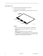
Chassis Model 5011 – 1-slot chassis which can be placed on a tabletop or 
installed in a rack.

„

Chassis Model 5016 – 6-slot chassis which must be installed in a commercial 
EIA-standard 19

 or 23

 rack or cabinet. 

Summary of Contents for Hotwire 6050

Page 1: ...e DSL Digital Subscriber Line and POTS frequencies Simultaneous access to POTS and data requires the installation of a POTS splitter at the CO for ADSL G Lite Adaptive DSL RADSL Rate Adaptive DSL ReachDSL MVL Multiple Virtual Lines TDM SDSL Time Division Multiplexer Symmetric DSL POTS Splitter Chassis The Hotwire POTS splitter card is mounted in a Hotwire POTS Splitter Chassis Two chassis models a...

Page 2: ...re 6050 Universal POTS Splitter Card is compatible with ADSL Any product compliant with standard T1 413 Issue 2 and or G 992 1 Type 2 RADSL All Hotwire RADSL line cards providing POTS ReachDSL MVL All Hotwire ReachDSL MVL line cards providing POTS All references to DSL cards in this document refer to ADSL MVL RADSL and ReachDSL unless specifically noted otherwise DSL Interface Loop Interface PSTN ...

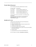
Page 3: ...s you need Preparing the installation location and checking the package contents Installing the POTS splitter chassis Inserting the POTS splitter card s into the chassis Connecting the cabling from the POTS splitter card connectors to the DSLAM local loop and PSTN switch Securing the cables Verifying the firmware level of the port cards TDM SDSL only Be sure to register your warranty at www parady...

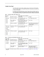
Page 4: ... connectors One 6050 POTS splitter card to six 4 port DSL cards Cable with single connector to six cables with single connectors via connector block 12 port cards 8312 8314 8365 8373 8374 8610 8810 or 8820 rear connectors One 6050 POTS splitter card to two 12 port DSL cards One Y cable 12 port cards 8314 8365 8374 8620 rear connectors One 6050 POTS splitter card to two 12 port DSL cards One Y cabl...

Page 5: ...quired A small 1 or 2 Phillips screwdriver to tighten the POTS splitter card fasteners A large 3 or 4 Phillips screwdriver to install the chassis into a rack A flat blade screwdriver to install the chassis grounding wire Hotwire 6050 or 7020 POTS Splitter Card Package Checklist Verify that your POTS splitter card package contains the following POTS splitter card Plastic bag with three of each item...

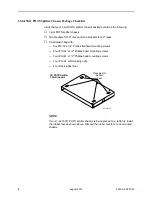
Page 6: ...plastic bag with Six 10 32 x 1 4 Phillips flat head mounting screws Four 10 32 x 1 2 Phillips head mounting screws Four 12 24 x 1 2 Phillips head mounting screws Four 12 24 self retaining nuts Four black rubber feet NOTE If your 1 slot 5011 POTS splitter chassis is being placed on a tabletop install the rubber feet as shown above Discard the rubber feet for a rack mounted chassis 99 15497 02 CO PO...

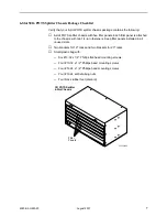
Page 7: ...ed to the chassis with two 1 4 turn fasteners Keep filler panels installed in all unused slots Two brackets for 19 racks and two brackets for 23 racks Small plastic bag with Six 10 32 x 1 4 Phillips flat head mounting screws Four 10 32 x 1 2 Phillips head mounting screws Four 12 24 x 1 2 Phillips head mounting screws Four 12 24 self retaining nuts Four black rubber feet discard 99 15430 02 CO POTS...

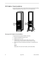
Page 8: ...ermine Whether the DSLAM will be rack mounted Width of the rack 19 or 23 Chassis position in the rack center mounted or front mounted Center mounting is recommended for convenient access to cables Whether the rack has mounting rails with threaded or non threaded screw holes NOTE Install chassis in the rack from the bottom up to maintain stability 00 15426b ALARMS Major Minor Fan B A POWER A B ALAR...

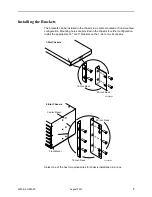
Page 9: ...on Mounting holes are provided in the chassis for either configuration Install the appropriate 19 or 23 brackets on the 1 slot or 6 slot chassis Select one of the next two procedures for chassis installation in a rack 19 Inch Rack 23 Inch Rack 99 15486 02 1 Slot Chassis 19 Inch Rack 23 Inch Rack 99 15434 02 Front Mount Center Mount 6 Slot Chassis ...

Page 10: ...will be 2 Slide a self retaining nut onto each marked rail hole and align the hole of the nut with the hole in the rail 3 Line up the chassis mounting brackets with the self retaining nuts 4 Loosely install the bottom screws first and then the top screws 5 Tighten all screws firmly using a Phillips screwdriver Repeat the process for each POTS splitter chassis POTS splitter chassis can be mounted d...

Page 11: ...e chassis will be placed in the rack 2 Line up the chassis mounting brackets with the front rail holes 3 Loosely install the bottom screws first and then the top screws 4 Tighten all screws firmly with a Phillips screwdriver Repeat the process for each POTS splitter chassis POTS splitter chassis can be mounted directly on top of each other Front Rail 99 15435 01 Screw ...

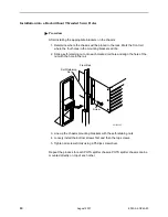
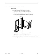
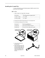
Page 12: ... grounding lug 5 Insert the stripped end of the wire into the open end of the grounding lug and tighten the lug s screw Make sure that the screw is making contact with the stripped portion of the wire If you have a Then the ground wire gauge must be 1 slot 5011 chassis 10 14 AWG 6 slot 5016 chassis 6 14 AWG If you have a Then the grounding lug is 1 slot chassis On the rear of the chassis on the le...

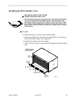
Page 13: ...ure of the proper static control precautions contact your nearest sales or service representative Procedure To install a POTS splitter card into the POTS splitter chassis 1 Remove the slot filler panel if necessary by loosening the 1 4 turn fastener on either side Keep filler panels in all unused slots 2 Slide the POTS splitter card into the chassis 3 Tighten the 1 4 turn fastener on each side of ...

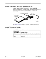
Page 14: ...Y cable to the 8610 DSLAM See Cables You Need on page 4 for information about POTS splitter cabling Cabling to 4 Port DSL Cards The POTS splitter card has three interfaces CO POTS Splitter 1 Slot Chassis Supporting 24 Ports 00 16333 02 Rear View of 8610 Chassis Y Cable with 2 Connectors Supporting 12 Ports Each Use the interface connector labeled To connect to the DSL DSL interface on the Hotwire ...

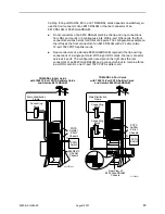
Page 15: ...ons of a single port card With 4 port DSL cards the rear connector services 4 ports The configuration example on the right uses the rear connectors of an 8820 GranDSLAM and a connector block to combine three 4 port DSL cards to one 12 port 7020 POTS splitter card TM TM 00 15550a 03 ALARMS Major Minor Fan B A POWER A B 8800 8810 DSLAM Chassis POTS Splitter 6 Slot Chassis Connecting Block PSTN Switc...

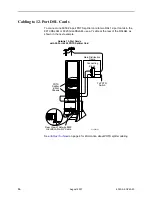
Page 16: ... rear of the DSLAM as shown in the next example See Cables You Need on page 4 for information about POTS splitter cabling TM TM 01 16921 01 POTS Splitter 6 Slot Chassis To PSTN Switch Hotwire 12 Port Cards with 24 Port 6050 POTS Splitter Card 18 17 16 15 14 13 12 11 10 9 8 7 6 5 4 3 2 1 6 5 4 3 2 1 Rear View of Hotwire 8820 GranDSLAM with Y Cable Connecting Block Main Distribution Frame ...

Page 17: ...p through the anchor from the top 2 Attach the cable head to the POTS splitter connector If the connector on the cable has a long screw tighten the screw directly into the connector located in the circuit card Discard the jack screws provided If the connector on the cable has a short screw install the 4 40 jack screw provided into the threaded hole of the connector in the circuit card Attach the s...

Page 18: ... 20 3 Tighten the tie wrap and trim the excess Repeat the procedure for all the interface cables 00 15553 01 POTS Splitter Card Faceplate TM 99 15432 01 CO POTS Splitter 6 Slot Chassis DSL Interface Loop Interface PSTN Interface ...

Page 19: ...entative The Paradyne Web site is www paradyne com 2 On the Download Page locate and click on the download file for version P6 02 00 or above Save the file on your PC 3 The file is compressed Execute the file on your PC to expand it This creates a file with the suffix ocd Move the file if necessary to a directory accessible to your TFTP server Procedure To download software from your TFTP server u...

Page 20: ...s 50 Position Telco Connector 6050 uses 24 pairs 7020 uses the first 12 pairs CO POTS Splitter Pin Ring Pin Tip 1 1 26 2 2 27 3 3 28 4 4 29 5 5 30 6 6 31 7 7 32 8 8 33 9 9 34 10 10 35 11 11 36 12 12 37 13 13 38 14 14 39 15 15 40 16 16 41 17 17 42 18 18 43 19 19 44 20 20 45 21 21 46 22 22 47 23 23 48 24 24 49 Pin 25 98 15482 01 Pin 1 Pin 50 Pin 26 ...

Page 21: ...e part number is 8000 F1 001 Y Cable Wiring P1 Connector Pin s To P2 or P3 1 13 1 2 14 2 3 15 3 4 16 4 5 17 5 6 18 6 7 19 7 8 20 8 9 21 9 10 22 10 11 23 11 12 24 12 26 38 26 27 39 27 28 40 28 29 41 29 30 42 30 31 43 31 32 44 32 33 45 33 34 46 34 35 47 35 36 48 36 37 49 37 P1 P2 Pairs 1 12 P3 Pairs 13 24 Captive Screw Captive Screw 00 15806 02 Y Cable P2 To 1 12 P3 To 13 24 Captive Screw ...

Page 22: ... 17 2 x 9 94 22 15 cm x 43 69 cm x 25 29 cm Weight empty 6 0 lb 2 13 kg Approvals Safety Certifications Refer to the equipment s label for approvals on product POTS Splitter Cards Technical Specifications Height x Width x Depth Models 6050 7020 1 07 x 15 77 x 9 77 2 72 cm x 40 06 cm x 24 82 cm Weight Model 6050 Model 7020 2 6 lb 1 19 kg 5 4 lb 2 45 kg Compliance 6050 Universal Line Sharing T1 413 ...

Page 23: ...compliance 6 In addition since the equipment is to be used with telecommunications circuits take the following precautions Never install telephone wiring during a lightning storm Never install telephone jacks in wet locations unless the jack is specifically designed for wet locations Never touch uninsulated telephone wires or terminals unless the telephone line has been disconnected at the network...

Page 24: ...presentative Within the U S A call 1 800 870 2221 Outside the U S A call 1 727 530 2340 Document Feedback We welcome your comments and suggestions about this document Please mail them to Technical Publications Paradyne Corporation 8545 126th Ave N Largo FL 33773 or send e mail to userdoc paradyne com Include the number and title of this document in your correspondence Please include your name and ...

Reviews: