background image

80

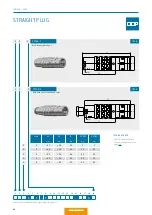
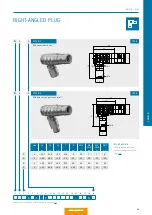
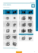
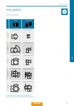
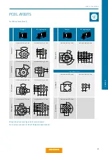
STRAIGHT PLUG

With standard back nut

With back nut for cable bend relief

1

Please order cable bend reliefs separately, see page 111.

TECHNICAL DATA

• 

 IP 68 in mated condition.

• 

 Contact con

fi

guration from 

page 90.

Size

L1 

mm

L2 

mm

mm

S1 SW


mm

S2 SW 

mm


0

≈ 37 

≈ 26

11

7

7

1

≈ 44

≈ 30

13

10

10

2

≈ 50

≈ 34

16

12

13

3

≈ 60

≈ 40

19

14

15

4

≈ 73

≈ 52

25

20

20

0

1

2

3

4

S

1

S

2

1

2

3

4

5

6

7

8

9

10

11

12

13

14

15

16

17

18

19

K

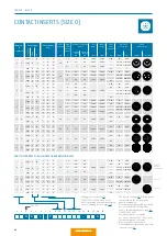
C – P

0

IP 68

IP 68

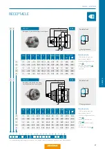
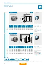
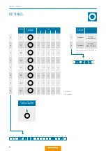
SERIES K – PLUG

0

S

STYLE: 1

STYLE: 2

L1

L2

D

SW

L1

L2

D

SW

Table of Contents

Summary of Contents for MINI-SNAP K Series

Page 1: ...K www odu usa com A PERFECT ALLIANCE ODU MINI SNAP Miniature circular connectors with Push Pull locking ODU MINI SNAP K ODU MINI SNAP L ODU MINI SNAP B ODU MINI SNAP F ODU AMC ODU MEDI SNAP ODU MINI S...

Page 2: ...NAP is UL approved under file E110586 MIL specification Tests carried out see page 170 All dimensions are in mm Some figures are for illustrative purposes only Subject to change without notice Errors...

Page 3: ...TION PROCESSING INSTRUCTIONS ACCESSORIES 154 156 158 158 Crimping tools assembly tools Spanner wrench Nutdriver for slotted mounting nut Removal tools for crimp clip contacts 159 TECHNICAL INFORMATION...

Page 4: ...ING INTO THE FUTURE WHETHER TWO TECHNICAL COM PONENTS COME TOGETHER TO FORM A UNIT OR PEOPLE COME TOGETHER TO STRIVE FOR GREAT RESULTS THE KEY IS TO ASPIRE IN ACHIEVING SUPERB RESULTS THIS GOAL DRIVES...

Page 5: ...g turning surface technology assembly and cable assembly As of February 2018 CERTIFIED QUALITY DIN EN ISO 9001 IATF 16949 DIN EN ISO 14001 ISO 13485 Wide range of UL CSA VG and DVA licenses UL certifi...

Page 6: ...The highest packing density Flexible modular construction Multitude of data transmission modules Variety of locking options available For the transmission of signals power high current high voltage c...

Page 7: ...mples Extremely durable even under extreme harsh environments Interference free and secure connection even under vibration Up to 500 A higher currents upon request High contact security due to the spr...

Page 8: ...ons of our products especially for the ODU MINI SNAP and ODU MAC connectors MORE THAN A CONNECTION OUR KNOW HOW FOR YOUR SUCCESS HIGH PERFORMANCE CONNECTOR TECHNOLOGY FOR DEMANDING KEY MARKETS Custome...

Page 9: ...on injection stamping turning surface tech nology assembly and cable assembly and our own test laboratory INDIVIDUAL CABLE ASSEMBLY Our production skills together with our cutting edge production faci...

Page 10: ...ODU MINI SNAP Table of Contents...

Page 11: ...T INFORMATION Push Pull connector series at a glance 12 Specific attributes of the series L K and B 13 Functional principle of the Push Pull locking 14 Facts figures 15 PRODUCT INFORMATION Table of Co...

Page 12: ...TOR SERIES ODU MINI SNAP L ODU MINI SNAP K ODU MINI SNAP B Keying over half shell 2 27 contacts Low weight IP 67 3 sizes Plastic connector plug housing ODU MINI SNAP PC ODU MEDI SNAP ODU MINI SNAP S K...

Page 13: ...characteristics The Push Pull principle reliably ensures that the connector will not come loose during application in practice Once plugged in the ODU MINI SNAP locks itself into the receptacle autom...

Page 14: ...ed from the receptacle by pulling on the outer housing 3 Push pull connectors from ODU are avail able in 6 different standard sizes with diameters from 6 4 mm to 25 mm You can read about the precise f...

Page 15: ...chrome plated connector plug housings are available upon request as special materials The internal parts are made of nickel plated brass Thanks to its versatility and autoclavability the ODU MINI SNAP...

Page 16: ...ODU MINI SNAP Table of Contents...

Page 17: ...CONFIGURATION GUIDELINE Correct configuring step by step CONFIGURATION Table of Contents...

Page 18: ...rvice for the complete assembly From connectors to watertight grouting we provide the complete system from a single source BIT BY BIT TO THE PERFECT CONNECTION Back nut Cable collet Half shells Insula...

Page 19: ...ials on request 2 Black chrome plated on request Connector plug housing Series L from page 28 series K from page 80 series B from page 120 Cable entry Series L from page 64 series K from page 108 seri...

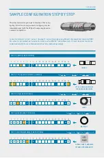
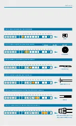
Page 20: ...11 12 13 14 15 16 17 18 19 L C P 0 1 2 3 4 5 6 7 8 9 10 11 12 13 14 15 16 17 18 19 S 2 2 L C P 0 S 1 2 3 4 5 6 7 8 9 10 11 12 13 14 15 16 17 18 19 S 2 2 L 0 C P 0 S 1 2 3 4 5 6 7 8 9 10 11 12 13 14 1...

Page 21: ...M F G 0 0 S SOLDER PIN PEEK 16 CONTACTS AWG 22 1 2 3 4 5 6 7 8 9 10 11 12 13 14 15 16 17 18 19 S 2 2 L 0 C P 1 6 M F G 0 7 2 0 S MAX CABLE DIAMETER 7 2 mm MIN CABLE DIAMETER 6 mm CONFIGURATION STEP 7...

Page 22: ...ODU MINI SNAP Table of Contents...

Page 23: ...MINI SNAP SERIES K Summary ODU MINI SNAP series K 76 The LP locking principle 78 Styles 80 Keyings 88 Contact inserts and PCB Layouts 90 Cable collet system 108 Accessories 110 SERIES K Table of Conte...

Page 24: ...ured in many dif ferent ways a wide variety of sizes and termination types and contact inserts are available Keying over pin and groove 2 40 contacts mixed inserts Up to 5 sizes and 3 termination type...

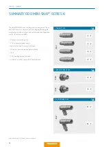
Page 25: ...MARY RECEPTACLE G 1 G 3 G L G 4 G 8 IN LINE RECEPTACLE K 1 K 2 For assembly instructions please refer to our website www odu connectors com downloads assembly instructions P 85 P 84 IP 68 1 IP 68 1 IP...

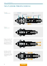
Page 26: ...in the recep tacle s locking groove This prevents the connector from being disconnected THE LP LOCKING PRINCIPLE SERIES K Grounding ring Locking groove Locking fingers jaws Outer housing Back nut REC...

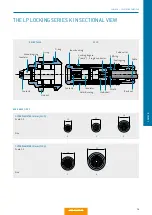
Page 27: ...nductor EMI ring Sealing ring Cable collet Cable Insulator Size Size RECEPTACLE PLUG OUTER DIAMETER IN mm PLUG Scale 1 1 OUTER DIAMETER IN mm PLUG Scale 1 1 6 4 9 11 5 00 C1 0 1 2 3 4 14 5 Serie L Ser...

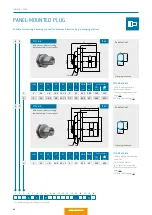
Page 28: ...ATA IP 68 in mated condition Contact configuration from page 90 Size L1 mm L2 mm D mm S1 SW mm S2 SW mm 0 37 26 11 7 7 1 44 30 13 10 10 2 50 34 16 12 13 3 60 40 19 14 15 4 73 52 25 20 20 0 1 2 3 4 S 1...

Page 29: ...act configuration from page 90 Plug can be separated by pulling on the cable Size L1 mm L2 mm D mm A1 SW mm A2 SW mm 0 37 26 11 7 7 1 44 30 13 10 10 3 60 40 19 14 15 0 1 3 A 1 A 2 With back nut for ca...

Page 30: ...ition Anti rotation feature No crimp contact possible Contact configuration from page 90 PCB layouts see page 91 With hex nut without locking installation from front of panel SW 0 1 0 1 SW 0 1 0 1 IP...

Page 31: ...ANGLED PLUG W 1 W 2 0 1 2 3 Size L1 mm L2 mm L3 mm C mm D mm SW A mm W1 SW B mm W2 SW B mm SW C mm 0 34 7 23 2 27 11 6 9 10 7 7 8 1 43 28 7 34 14 11 12 10 10 10 2 51 34 7 36 17 5 14 15 12 13 13 3 61 4...

Page 32: ...condition Contact configuration from page 90 Size L1 mm D mm SW A mm K1 SW B mm K2 SW B mm 0 39 13 9 7 7 1 47 15 11 10 10 2 54 19 14 12 13 3 64 23 16 5 14 15 4 79 29 22 20 20 0 1 2 3 4 With back nut...

Page 33: ...C mm Panel cut out SW mm mm 0 21 5 5 15 5 14 1 18 12 5 17 4 12 6 14 1 1 28 9 20 5 16 1 20 14 5 19 4 5 14 6 16 1 2 31 9 23 20 1 25 18 5 24 5 18 6 20 1 3 36 11 28 24 1 31 22 5 30 6 22 6 24 1 2 40 11 31...

Page 34: ...figuration from page 90 Right angled PCB contact possible see page 106 Note assembly wrench see page 158 Size L11 mm L2 mm L32 mm M mm D 1 mm D 2 mm SW A mm C mm Panel cut out SW mm mm 1 32 6 26 6 16...

Page 35: ...mm M mm D mm C mm SW A mm SW B mm Panel cut out SW mm mm 0 24 5 19 7 14 1 18 4 12 5 17 12 6 14 1 1 32 9 26 6 16 1 20 4 5 14 5 19 14 6 16 1 2 34 9 27 20 1 25 5 18 5 24 18 6 20 1 Installation from fron...

Page 36: ...Reihe K 0 30 45 60 75 95 120 145 Reihe K 0 30 45 60 75 95 120 145 Reihe K 0 30 45 60 75 95 120 145 Reihe K 0 30 45 60 75 95 120 145 Reihe K 0 30 45 60 75 95 120 145 Reihe K 0 30 45 60 75 95 120 145 Re...

Page 37: ...89 SERIES K SERIES K FOR YOUR NOTES Table of Contents...

Page 38: ...0 15 0 6 0 6 0 900 0 300 0 85 22 0 38 22 26 0 38 0 15 0 5 CONTACT INSERTS SIZE 0 1 Derating factor see page 167 2 SAE AS 13441 2004 method 3001 1 3 Tools for crimping and adjustment dimen sions for c...

Page 39: ...1 27 2 54 2 54 1 2 3 4 5 6 For PCB contacts Size 0 All specifications are only valid for socket inserts Pin inserts on request Further PCB layouts upon request Straight 90 right angled 7 contacts Con...

Page 40: ...0 9 0 9 1 200 0 400 28 32 0 09 0 04 0 5 Number of contacts 0 2 0 3 0 4 0 5 0 6 Contacttype Termination Socket Pin Solder L M Crimp3 N P PCB4 R Solder L M Crimp3 N P PCB4 R Solder L M Crimp3 N P PCB4...

Page 41: ...ehole 0 8 mm Contact borehole 0 7 mm 6 contacts Contact borehole 0 6 mm Contact borehole 0 7 mm 2 1 2 8 1 2 2 54 2 1 3 1 2 0 3 2 3 1 4 90 3 1 2 3 4 1 5 7 2 3 5 1 2 3 4 5 6 60 3 7 2 3 4 5 6 1 2 54 2 54...

Page 42: ...R Solder L M Print4 Q R Solder L M Print4 Q R Solder L M Crimp3 N P Print4 Q R Solder L M Print4 Q R Part number key F G 0 F D 0 F G 0 F C 0 F 0 0 F G 0 F D 0 F G 0 F C 0 F 0 0 C D 0 C C 0 C 0 0 C C 0...

Page 43: ...6 mm PCB LAYOUTS 6 60 3 7 7 2 3 4 5 6 1 2 54 2 54 1 27 1 2 3 4 5 6 7 7 51 4 3 8 2 3 4 5 6 7 8 1 2 54 2 54 2 54 1 27 2 3 4 5 6 7 8 9 10 1 2 54 2 54 2 54 2 54 1 27 2 3 4 5 6 7 8 9 10 11 12 13 14 1 2 54...

Page 44: ...85 22 0 38 0 7 0 6 0 900 0 300 20 24 0 50 0 25 1 0 9 1 500 0 500 22 26 0 38 0 15 0 7 Number of contacts 0 2 0 3 0 4 0 5 0 6 0 7 0 8 1 0 Part number key T S 0 T Q 0 T N 0 T 0 0 S N 0 S N 0 S L 0 S 0 0...

Page 45: ...e 0 8 mm Contact borehole 0 9 mm 10 contacts Contact borehole 0 8 mm Contact borehole 0 7 mm 6 60 5 8 2 3 4 5 6 7 1 8 45 6 4 2 3 4 5 6 7 8 1 1 27 2 54 2 54 2 54 2 3 4 5 6 7 8 9 10 1 2 54 2 54 1 27 1 2...

Page 46: ...0 F C 0 F 0 0 C C 0 C 0 0 P H 0 P H 0 P 0 0 J G 0 J G 0 J 0 0 Original Schlangekreisf 1 2 3 4 5 6 7 8 Original Schlangekreisf Original Schlange kreisf 1 2 3 4 5 6 7 8 1 2 3 4 5 6 7 8 Original Schlange...

Page 47: ...9 10 11 12 13 14 1 27 2 54 2 54 2 54 2 54 2 3 4 5 6 7 8 9 10 11 12 13 14 15 16 1 1 27 1 27 1 27 2 54 2 3 4 5 6 7 8 9 10 11 12 13 14 15 16 17 18 1 1 27 1 27 2 3 4 5 6 7 8 9 10 11 12 13 14 15 16 17 18 1...

Page 48: ...Q 0 T 0 0 T S 0 T Q 0 T 0 0 S N 0 S N 0 S L 0 S 0 0 P N 0 P H 0 P L 0 P H 0 P 0 0 P N 0 P H O P 0 0 J H 0 J G O J H 0 J G 0 J 0 0 Contacttype Termination Socket Pin Solder L M PCB4 R Solder L M PCB4 R...

Page 49: ...3 1 2 0 5 6 3 2 3 1 2 54 2 54 2 54 7 2 3 4 5 6 7 1 6 60 2 3 4 5 6 7 8 1 2 54 2 54 2 54 2 54 7 55 2 3 4 5 6 7 8 1 8 45 2 3 4 5 6 7 8 9 10 1 2 54 2 54 2 54 1 27 7 85 2 8 2 3 4 5 6 7 8 9 10 1 8 45 For P...

Page 50: ...1 000 0 333 0 85 22 0 38 0 9 1 9 1 100 0 366 0 6 26 0 15 0 7 1 7 1 000 0 333 22 26 0 38 0 15 0 9 1 9 1 100 0 366 28 32 0 09 0 04 0 5 0 5 0 6 0 900 0 300 0 85 22 0 38 0 7 0 8 1 000 0 333 0 6 26 0 15 0...

Page 51: ...1 2 54 2 54 2 54 2 54 2 54 2 54 1 27 5 8 8 2 3 4 5 6 7 8 9 10 11 12 13 14 15 16 17 18 19 20 21 22 1 14 25 7 8 45 2 1 9 5 6 2 3 4 5 6 7 8 9 10 11 12 13 14 15 16 17 18 19 20 21 22 23 24 26 25 1 14 25 7...

Page 52: ...22 0 38 0 8 1 1 000 0 333 0 6 26 0 15 0 5 Number of contacts 0 75 3 0 4 0 Contacttype Termination Socket Pin Solder L M PCB3 R Solder L M PCB3 R Solder L M PCB3 R Part number key T S 9 T Q 9 T 0 9 J...

Page 53: ...27 2 3 4 5 6 7 8 9 10 11 12 13 14 15 16 17 18 19 20 21 22 23 24 25 26 27 28 29 30 31 32 33 34 35 36 37 38 39 40 1 7 51 4 13 27 7 20 18 4 2 7 85 11 6 2 3 4 5 6 7 8 9 10 11 12 13 14 15 16 17 18 19 20 21...

Page 54: ...5 6 7 8 9 10 11 12 13 14 15 16 17 18 19 K C P 0 0 0 0 0 TECHNICAL DATA Pin version on request PCB layouts see page 91 RIGHT ANGLED PCB CONTACT for style G3 and G8 Contact diameter Termination diamete...

Page 55: ...107 SERIES K SERIES K FOR YOUR NOTES Table of Contents...

Page 56: ...6 6 6 5 6 5 7 7 7 5 7 5 8 8 8 5 8 5 9 9 9 5 9 5 10 10 10 5 10 5 11 5 13 5 14 Without cable collet system on request 1 2 3 4 5 6 7 8 9 10 11 12 13 14 15 16 17 18 19 K C P 0 APPLICATION For all plugs an...

Page 57: ...4 5 6 7 8 9 10 11 12 13 14 15 16 17 18 19 K C P 0 Usable for all straight right angled and Break Away connectors in line receptacles receptacles style 6 BACK NUT FOR SILICONE CABLE BEND RELIEF1 1 Plea...

Page 58: ...15 0 16 14 70 6 1 721 097 004 215 0 21 16 75 8 2 722 097 004 215 0 21 5 20 85 10 3 723 097 004 215 0 25 5 24 130 12 4 724 097 004 215 0 28 30 140 16 FOR RECEPTACLE TYPES FOR PLUG IP 68 Lanyard materia...

Page 59: ...023 965 040 4 5 702 023 965 050 5 6 702 023 965 060 6 7 702 023 965 070 7 8 702 023 965 080 8 9 3 703 023 965 040 42 4 5 703 023 965 050 5 6 703 023 965 060 6 7 703 023 965 070 7 8 703 023 965 080 8 9...

Page 60: ...nce Ring SW g direction B A Size Part number A mm B mm SW mm 0 700 022 117 3 002 8 8 9 7 1 701 022 117 3 002 10 10 9 10 2 702 022 117 3 002 11 5 13 9 13 3 753 022 117 3 002 11 5 16 9 15 4 704 022 117...

Page 61: ...113 SERIES K SERIES K FOR YOUR NOTES Table of Contents...

Page 62: ...ODU MINI SNAP Table of Contents...

Page 63: ...TOOLS The following pages contain tools and wrenches to ensure that your ODU connectors function flawlessly TOOLS Table of Contents...

Page 64: ...001 000 4 7 1 3 20 24 0 5 0 25 0 67 080 000 051 106 000 5 6 087 7CC 130 001 000 4 7 1 3 18 20 1 0 5 1 12 080 000 051 106 000 5 6 087 7CC 130 001 000 3 1 6 18 20 1 0 5 1 12 080 000 051 107 000 1 2 087...

Page 65: ...702 001 848 037 081 702 001 748 037 3 3 087 7CC 070 001 000 12 19 0 7 22 26 0 38 0 15 081 702 001 848 037 081 702 001 748 037 4 4 087 7CC 070 001 000 8 10 0 9 22 26 0 38 0 15 081 701 002 849 037 081 7...

Page 66: ...5 145 15 598 700 001 023 000 18 3 42 172 16 598 700 001 013 000 19 3 42 172 16 598 700 001 009 000 20 3 42 172 16 598 700 001 018 000 21 3 42 172 16 598 700 001 010 000 22 3 47 119 23 5 598 700 001 0...

Page 67: ...CC 070 001 000 0 7 087 7CC 090 001 000 0 9 087 7CC 130 001 000 1 3 087 7CC 160 001 000 1 6 087 7CC 200 002 000 2 Removal tool Crimp clip contact PART NUMBER 080 000 055 000 000 Suitable from size 0 to...

Page 68: ...ODU MINI SNAP Table of Contents...

Page 69: ...ODU connectors ensure perfect and reliable transmission of power signal data and other media in a wide variety of applications Further information can be found on the following pages TECHNICAL INFORMA...

Page 70: ...rotection against solid foreign objects 2 5 mm 3 Protection against spray water Protection against spray water any angle up to 60 of the vertical 4 Protection against granular foreign objects Protecti...

Page 71: ...MINI SNAP PROTECTION AGAINST WATER BY THE FOLLOWING SEALINGS1 1 The following applies to the contacts the contacts are protected in cases 1 2 and 3 when mated When not mated the contacts are only pro...

Page 72: ...rt number key see page 39 series L page 88 series K page 125 series B Component Material designation Surface Connector plug housing Back nut Decorative slotted mounting nut Cu alloy Cr1 Cable collet E...

Page 73: ...to the individual wires via deformation in the termination area Then the contacts are individually installed in the insulator Accordingly insulators and individual contacts and not complete contact i...

Page 74: ...0 5 26 46 77 3 45 10 37 26 0 1150 2 921 4 74 42 10 4 13 12 1 0 0808 2 050 3 31 29 41 5 45 12 19 25 0 0930 2 362 3 08 27 36 6 14 12 37 28 0 0910 2 311 2 97 26 45 6 36 14 1 0 0641 1 630 2 08 18 51 8 79...

Page 75: ...0 35 40 45 50 55 60 6 6 5 4 3 2 1 7 6 5 4 3 2 1 5 4 3 2 1 7 6 5 4 3 2 1 UPPER LIMIT TEMPERATURE OF STANDARD CONTACTS 120 C The wire cross section shown in the legend was connected as test cable In the...

Page 76: ...be factored in according to the applicable standards Test voltage Dielectric withstanding voltage 0 75 Operating voltage Dielectric withstanding voltage 0 75 0 33 ATTENTION With certain applications...

Page 77: ...is attached as closely as possible along the connector pair A flat cable is usually used here since an optimum adjustment can be achieved by attaching more or fewer wires High frequency signals in th...

Page 78: ...Watertightness IP 68 IEC 60529 2013 VDE 0470 1 2014 AUTOCLAVING OF ODU MINI SNAP We can also provide ODU MINI SNAP connectors for the following sterilization procedures upon request steam sterilizatio...

Page 79: ...se the resistance is significantly lower than the contact resistance The specifications are average values CORES Electrical conductor solid wire or multi wire strand with insula tion as well as any co...

Page 80: ...he contact temperature to the limit temperature The values specified in the catalog apply to either individual contacts or completely assembled inserts modules as indicated NOMINAL SINGLE CONTACT CURR...

Page 81: ...E The maximum permissible temperature at which a connector may be operated It includes contact heating through cur rent carrying capacity With ODU MINI SNAP Standard TURNTAC contacts it amounts to 120...

Page 82: ...es odu denmark dk www odu denmark dk ODU France SARL Phone 33 1 3935 4690 E mail sales odu fr www odu fr ODU Italia S R L Phone 39 331 8708847 E mail sales odu italia it www odu italia it ODU Japan K...

Reviews: