4 VCF
Card
4.1
Theory of Operation
The Voltage Controlled Filter Card (VCF Card) consists of four identical
four-pole (-24dB/Octave) VCF circuits based on the SSM 2044
Integrated Filter. One card is used for the LEFT side of the instrument
and the other for the RIGHT side of the instrument. Both cards are
identical and may be interchanged to facilitate troubleshooting.
The functions on this board include:
•
Four filter circuits each with Voltage Controlled Cutoff (F
c
) and
Resonance (Q).
•
Voltage Controlled Oscillator (VCO) volume amplifiers for VCO1
and VCO2 on four voices.
•
Modulation system demultiplexers for VCO1, VCO2 Filter Cutoff
(F
c
) and Resonance (Q).
•
VCO1 and VCO2 multiplexing for the modulation/tuning system.
4.2 VCF
Operation
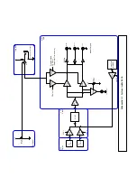
The SSM2044 is a four-pole filter with a current input and current output.
The input consists of the output currents of the VCO volume VCAs and
the noise voltage dropped across the 100K noise input resistors, while
the output current is converted to a voltage by the voltage-to-current
converter opamp inverter TL082 U12. This output is routed to the mixer
card.
The filter audio inputs include VCO1, VCO2 and Noise. The noise source
is generated on the MIXER card and is routed to all four VCFs
simultaneously. The VCO1 and VCO2 volume levers are determined by
two SSM 2024 Quad Voltage Controlled Amplifier (VCA) ICs. The control
voltage for these ICs is generated by the CPU at positions 4 and 5 on
demultiplexer CD4051, U3.
VCO1 may bypass the VCF using the MC14551 quad switch to route the
output current directly into the current-to-voltage converter at the output
of the SSM 2044. The position of this switch is determined by the control
signal on pin 6 which is generated on the DAC and controlled by the
CPU. The resistive current divider at the VCO 1 output to the VCF is
used to balance the relative gains of VCO1 in the normal and bypass
modes.

