background image


BA_OCHSNER AIR EAGLE_414_717_V06_EN.docx


Page 23 of 76


 Transport and handling 


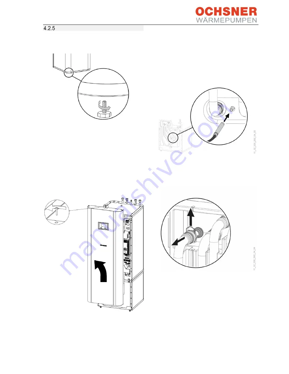
Remove the 4 screws from the non-
returnable pallet. 


Figure 26: 

Removing the fixing screw 


Slightly tilt the appliance and screw in the  
4 adjustable feet supplied. 

Lift the appliance from the pallet. 


Should  narrow  doors  or  corridors  impede 
handling,  the  top  and  bottom  sections  of  the 
appliance  can  be  separated  as  described  in  the 
following sections. 
 

Removing the front cladding: 


Remove the screw from the top centre of the 
appliance. 

Unhook the front cladding towards the top. 

Disconnect the control panel plug and the 
front panel earth wire. 


Installing the front cladding 
 

Install the front cladding in reverse order. 
 

Separating the appliance sections: 


Figure 27: 

Pull the sensor from the buffer tank.


Pull out the sensor on the buffer tank. 

Remove the sensor cable from the guiding 
groove in the insulation element. 


Figure 28: 

Undoing the plug-in connectors


Undo the plug-in connectors of the 4 hydraulic 
connections. Pull out the spring clips fully 
using a screwdriver.  

Pull off the hydraulic connections towards the 
front. 
 

Summary of Contents for Air Eagle 414

Page 1: ...06_EN docx Page 1 of 76 Operating and installation manual OCHSNER AIR EAGLE 717 OCHSNER AIR EAGLE 414 OCHSNER AIR EAGLE 717 with MULTI TOWER T200 OCHSNER AIR EAGLE 414 with MULTI TOWER T200 Air water...

Page 2: ...BA_OCHSNER AIR EAGLE_414_717_V06_EN docx Page 2 of 76...

Page 3: ...g 34 6 10 Pumps drives 230 VAC 35 6 11 HLSC on the heating circuit 35 6 12 DHW booster heater 35 6 13 Wiring diagram 36 6 14 Indoor unit wiring 37 Golf Midi indoor unit 37 T200 MULTI TOWER indoor unit...

Page 4: ...ettings The appliance must not be converted or modified in any way Work on the appliance repairs modifications may only be carried out by the manufacturer or bodies authorised by them Turn off all mai...

Page 5: ...mponents are made of powder coated stainless steel Includes all components and safety relevant devices required for operation Contains non flammable safety refrigerant Two different indoor units are a...

Page 6: ...air humidity condenses as ice on the evaporator fins This ice is automatically removed defrosting In the defrost phase the fan shuts down and the heat pump circuit is reversed The heat required for de...

Page 7: ...mode Avoid installation in an open and exposed location with high expected wind loads e g flat roof of a house in a raised location Select an installation location where the appliance is on the side...

Page 8: ...e 8 of 76 Minimum wall clearances Do not place the outdoor unit in a recess The diagram shows the minimum wall clearances Figure 3 Outdoor unit minimum clearances in mm Dimensions Figure 4 Outdoor uni...

Page 9: ...on of the refrigeration and electric system We recommend securing the outdoor unit before removing the casing cover Procedure 1 Secure the outdoor unit 2 Undo screws on the cover 3 Lift cover out 4 Re...

Page 10: ...d cables passed through When everything is ready re align the mounting plate and tighten the cable entries Figure 6 Outdoor unit conduits Outdoor unit control box Compressor Fan motor Inverter Refrige...

Page 11: ...This must be done in accordance with the relevant Building Codes of Practice and regulations Take the expected wind loads at the installation site into consideration Ensure that the outdoor unit is a...

Page 12: ...lines where installed underground 3 Gravel bed 4 Drainage pipe frostproof Figure 8 Strip foundation dimensions in mm Spot foundation 1 Spot foundation 2 Pipe liner for the connecting lines where insta...

Page 13: ...s of roof structure loads allow for an ice load of 400 kg m in addition to the dead weight of the outdoor unit When installing the EAGLE outdoor unit on top of a freestanding car port a garage or a st...

Page 14: ...et 4 Washer 5 Fixing screw Figure 11 EAGLE outdoor unit secured with structure borne noise attenuating fixings 1 Flat roof 2 Refrigerant lines in open air with thermal insulation and UV protection 3 B...

Page 15: ...all and recesses when installing the unit and ensure the maximum room temperature does not exceed 30 C 4 1 Golf Midi indoor unit Main components Figure 13 Indoor unit detailed view Indoor unit control...

Page 16: ...ocation 4 1 3 1 Minimum wall clearances Figure 15 Minimum wall clearances Room temperature 30 C Controller voltage 230 V Booster heater 400 VAC Sensors 12 V Liquid line DHW heating return Heating retu...

Page 17: ...EAGLE_414_717_V06_EN docx Page 17 of 76 4 1 3 2 Dimensions Figure 16 Indoor unit dimensions Figure 17 Indoor unit tilt height Figure 18 Indoor unit connection dimensions min 50 mm 1150 mm 400 mm 650 m...

Page 18: ...filling A 24 l expansion vessel is installed in the heat pump Golf Midi indoor unit In buffer systems or systems with higher capacity this expansion vessel should be checked If required install an add...

Page 19: ...g valve emergency booster heater for mono energetic operation 4 2 1 1 DHW tank The steel tank is fitted internally with a special direct enamel and a sacrificial anode The anode with wear indicator pr...

Page 20: ...MFA 17 Air vent valve Figure 22 Main components in T200 indoor unit Choosing the installation location CAUTION Do not install the appliance in damp rooms Install the appliance in a frost free and dry...

Page 21: ...E_414_717_V06_EN docx Page 21 of 76 4 2 3 1 Minimum wall clearances Figure 23 Minimum clearances in mm Minimum clearances to the side can be either to the right or the left 4 2 3 2 Dimensions Figure 2...

Page 22: ...union nut with flat gasket e02 Heating return 1 union nut with flat gasket e50 Hot gas line e51 Liquid line c01 Cold water inlet 1 union nut with flat gasket c06 DHW outlet 1 union nut with flat gaske...

Page 23: ...ladding Remove the screw from the top centre of the appliance Unhook the front cladding towards the top Disconnect the control panel plug and the front panel earth wire Installing the front cladding I...

Page 24: ...ions 1 Pull the top section towards the front Figure 32 Separating the appliance sections 2 Tilt the top section towards the back Use the grip rail for better grip during transport Figure 33 Setting d...

Page 25: ...36 Assembling the appliance sections 2 Slide the top appliance section towards the rear until it is flush with the bottom section When the appliance sections are assembled correctly the end position...

Page 26: ...astic CAUTION A safety valve is required DHW line Permitted materials are stainless steel copper and plastic Installing the DHW circulation line A DHW circulation line with an external DHW circulation...

Page 27: ...valve to the OTE controller has been disconnected at the factory Once the system is successfully filled connect the plugs PIN3 N PE and PIN4 N PE on the OTE controller Filling the DHW tank Fill the DH...

Page 28: ...e heating circuit pump is the left hand pump in the upper section of the T200 Adaptor The adaptor needs to have the following dimensions Connections 2 x 1 MT with flat gasket Length 180 mm Nominal dia...

Page 29: ...en the DHW valves on all draw off points Figure 40 Draining the DHW tank Drain the DHW tank via the drain valve Cleaning and descaling the DHW tank CAUTION Do not use a descaling pump or descaling age...

Page 30: ...ING Work on the refrigerant circuit may be carried out only by an authorised and suitably qualified contractor o When handling refrigerant wear appropriate gloves protective clothing and protective gl...

Page 31: ...ference Figure 43 Oil lift bends A Liquid line B Hot gas line thicker copper pipe C Oil lift bend in the hot gas line min bending radius 5x diameter 5 2 Conduit to house Figure 44 Conduit to house dim...

Page 32: ...vices and equipment to disconnect and shut down all supply voltages across all poles which must be provided on the system side must meet the technical safety requirements of EN 60204 1 sections 5 and...

Page 33: ...connect GND to the screen 2x2x0 8 mm Table 1 Cable selection 6 3 Power connection details According to the wiring diagram see section 6 15 Wiring diagrams the 400 VAC and 230 VAC power supplies should...

Page 34: ...subscribers requires a twisted cable Cables of type Y ST Y 2x2x0 8 mm have proved to be suitable CAUTION Always use a twisted wire pair MODBUS A B eBus SIGNAL GND Do not connect GND to the screen 6 9...

Page 35: ...he top one third of the DHW tank or at the very least in the top half The lower the selected location of the DHW sensor the larger the switching hysteresis 5 15 K will need to be NOTE Ensure that the...

Page 36: ...unit Outdoor unit 5 W5 Control cable 230 VAC 23 24 L N PE 5x 1 5 mm Internal fuse protection Indoor unit Outdoor unit 6 W7 MODBUS 2x 2x 0 8 mm screened Indoor unit Outdoor unit 7 OTE TA outdoor temper...

Page 37: ...CAUTION Isolate the system from the power supply before attempting any electrical work CAUTION Connecting cable cross sections should be sized according to local regulations Golf Midi indoor unit Ter...

Page 38: ...rget value building management system BMS MODBUS B GND A Modbus connection to outdoor unit Note If the X11 terminal is not provided in the indoor unit control box on site provide an external junction...

Page 39: ...10 DHW auxiliary heater 1 2 EVU PSU signal contact 1 2 External high limit safety cut out heat sink Modbus B GND A Modbus connection to outdoor unit OTE pin Description 8 Heating circuit pump 2 with...

Page 40: ...ast 4 minutes after disconnecting the unit from the power supply to ensure all capacitors have been discharged From disconnection from power supply 4 minutes Terminal Description X4 L1 L2 L3 N PE Comp...

Page 41: ...Main distributor B Indoor unit control box C Outdoor unit control box 1 Compressor supply C16A across all poles 2 Controller supply C13A 3 Electric booster heater supply B16A across all poles 4 Optio...

Page 42: ...utor B Indoor unit control box C Outdoor unit control box 1 Compressor supply C16A across all poles 2 Controller supply C13A 3 Electric booster heater supply B16A across all poles 4 Option Supply for...

Page 43: ...supply C20A 2 Controller supply C13A 3 Electric booster heater supply a 3x 400 V B16A across all poles b 1x 230 V B40A 3a Booster heater with 3 phase power supply 3b Booster heater with single phase p...

Page 44: ...ply C20A 2 Controller supply C13A 3 Electric booster heater supply a 3x 400 V B16A across all poles b 1x 230 V B40A 3a Booster heater with 3 phase power supply 3b Booster heater with single phase powe...

Page 45: ...heating water Use the correct fill water that is suitable for the components of your heating system We recommend fill water prepared according to Guideline VDI 2035 2 A high pH value and low electric...

Page 46: ...no refrigerant will damage the appliance Operating circulation pumps without water in the system will destroy the pump The heat pump must be commissioned by OCHSNER customer service or an authorised O...

Page 47: ...tting the flow rate Figure 54 Reading the flow rate Heat consumption Heat pumps Circulation pump Item no Nominal flow rate heat sink Internal differential pressure Residual head OCHSNER AIR EAGLE 717...

Page 48: ...main menu with a diagram of the heating system is illustrated Each heat consumer heating circuits DHW circuits and each heat generator heat pump electric booster heater boiler etc has its own menu and...

Page 49: ...ng mode and the provision of high DHW temperatures when the bivalent point is not reached Emergency mode Should the heat pump fail due to a fault the heating output is provided by the electric emergen...

Page 50: ...heater for DHW DHW circulation hydraulics Reduce flow rate and use timer DHW heat exchanger scaled up Notify heating contractor clean heat exchanger descale DHW temperature not reached or no longer re...

Page 51: ...orator sensor check booster heater check refrigerant circuit OCHSNER 129 129 Er 48 TQE sensor faulty Replace sensor 130 130 Er 49 TQA sensor faulty Replace sensor 12 12 Er 50 Expansion valve Check fun...

Page 52: ...the settings or hydraulics If it is nevertheless not possible to identify or rectify the causes OCHSNER customer service is available to help 10 3 Rectifying minor causes independently Your heat pump...

Page 53: ...e www ochsner com We recommend testing the heating water system pressure and correcting it if necessary pressure too high low We recommend adjusting the pre charge pressure in the diaphragm expansion...

Page 54: ...requirements of the F gas regulations A correctly performed service not only helps to save energy but also protects the environment In addition correct care of the heating system is necessary to ensu...

Page 55: ...be isolated from the power supply by an authorised contractor Appliances with refrigerant should only be decommissioned by an authorised contractor refrigeration air conditioning heating The refrigera...

Page 56: ...1 7 5 5 1 4 COP EN 14511 4 2 4 Standard point A7 W55 Heating output range kW 6 6 8 6 3 9 11 0 Total heating output power consumption EN 14511 kW 8 6 2 7 6 4 2 1 COP EN 14511 3 3 3 1 Standard point A...

Page 57: ...at sink WNA internal Residual head I WNA external incl FM mbar 380 590 REFRIGERANT CIRCUIT EAGLE 717 EAGLE 414 No of refrigerant circuits pce 1 1 Refrigerant R410A R410A Defrost technology Hot gas Hot...

Page 58: ...st pressure bar 15 Draw off rate of DHW tank l min 25 BUFFER TANK Nominal capacity l 100 Material Steel Max operating pressure bar 3 Test pressure bar 4 5 Max permissible temperature C 95 Water hardne...

Page 59: ...SNER AIR EAGLE 717 PARA HPS 25 7 5 RKC 922586 1 8m h 30 l min 220 mbar In DHW mode 30 mbar 380 mbar 350 mbar OCHSNER AIR EAGLE 414 PARA HPS 25 7 5 RKC 922586 1 4 m h 23 l min 160 mbar In DHW mode 10 m...

Page 60: ...peratur C Eagle 717 0 1 2 3 4 5 6 7 8 23 21 19 17 15 13 11 9 7 5 3 1 1 3 5 7 9 1113151719212325 Leistungsaufnahme kW Lufttemperatur C Eagle 717 Heating output kW Air temperature C Air temperature C Po...

Page 61: ...79 indoor outdoor Sound power level dBA 57 0 Controller class with room remote control VI Controller contribution 4 Controller class without room remote control II Controller contribution 2 AIR EAGLE...

Page 62: ...BA_OCHSNER AIR EAGLE_414_717_V06_EN docx Page 62 of 76 13 9 Electrical wiring diagrams EAGLE 717...

Page 63: ...BA_OCHSNER AIR EAGLE_414_717_V06_EN docx Page 63 of 76...

Page 64: ...BA_OCHSNER AIR EAGLE_414_717_V06_EN docx Page 64 of 76...

Page 65: ...BA_OCHSNER AIR EAGLE_414_717_V06_EN docx Page 65 of 76...

Page 66: ...BA_OCHSNER AIR EAGLE_414_717_V06_EN docx Page 66 of 76...

Page 67: ...BA_OCHSNER AIR EAGLE_414_717_V06_EN docx Page 67 of 76 13 10 Electrical wiring diagrams EAGLE 414...

Page 68: ...BA_OCHSNER AIR EAGLE_414_717_V06_EN docx Page 68 of 76...

Page 69: ...BA_OCHSNER AIR EAGLE_414_717_V06_EN docx Page 69 of 76...

Page 70: ...BA_OCHSNER AIR EAGLE_414_717_V06_EN docx Page 70 of 76...

Page 71: ...BA_OCHSNER AIR EAGLE_414_717_V06_EN docx Page 71 of 76...

Page 72: ...r tank 23 Figure 28 Undoing the plug in connectors 23 Figure 29 Removing the hydraulic hoses 24 Figure 30 Undoing the connecting screws 24 Figure 31 Separating the appliance sections 1 24 Figure 32 Se...

Page 73: ...BA_OCHSNER AIR EAGLE_414_717_V06_EN docx Page 73 of 76 16 Declaration of conformity...

Page 74: ...BA_OCHSNER AIR EAGLE_414_717_V06_EN docx Page 74 of 76...

Page 75: ...BA_OCHSNER AIR EAGLE_414_717_V06_EN docx Page 75 of 76...

Page 76: ...rmepumpen GmbH Germany D 60314 Frankfurt a M Riederhofstra e 27 Hotline for system partners 49 0 1805 832840 Customer service hotline 49 0 69 256694 495 kontakt ochsner de www ochsner com OCHSNER W rm...

Reviews: