


Symphony SoundBite Demo User’s Guide
Freescale Semiconductor
5
Chapter 2
Using the Demonstration Application
At the factory, the EEPROM on the Symphony SoundBite is programmed with a demonstration application that also
doubles as the functional test software for the board during manufacture. The demonstration application allows you to do
“something” with the Symphony SoundBite board directly out of the box, without installing drivers or software.
2.1
Configuring the Jumpers and Switches
On board start-up, the demonstration application reads the status of the bank of 8 general purpose switches in the SW1 DIP
switch, which selects how the board passes/generates audio. This demonstration application originated from test software
written to allow the measurement of the audio performance of the various subsystems of the Symphony SoundBite with an
Audio Precision analyzer.
To restore the Symphony SoundBite to the original factory configuration and to provide a known starting point:
Set the switches and jumpers as indicated in Table 2-1, and choose the appropriate power source for the board (which is
fixed at the factory) that you want to use.
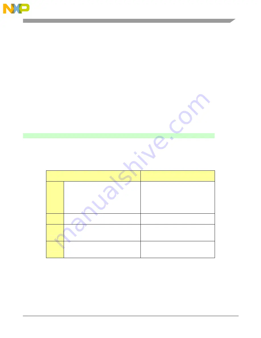
Table 2-1: Factory Default Configuration
Jumper or Switch
Effect
JP3
Jumper 2-3
or
Jumper 1-2
Board is powered from USB.
or
Board is powered from PWR_JACK.
JP3
Jumper 1-2, 3-4
Enable microphone input.
SW2
110110 (positions 654321, 1=ON)
Enable EEPROM and Boot Mode 9
(Boot from serial I
2
C EEPROM).
SW1
1000 0000 (positions 1234 5678,
1=ON)
J1 analog input passed to all outputs.