


8 Example communication peripheral connections
There are a wide range of peripheral pins available on the MCU. Many of these have fairly standard definitions for their use.
This section provides example connections for some of the most commonly used communications peripherals, such as LIN,
CAN, Ethernet, and RS-232 communication interfaces.
Table 13
summarizes the maximum communication speed and general overview information for the different types of
interfaces.
Table 13. Communication module comparison
Common
name
Standard
Distributed
timebase
Speed
(maximum
supported)
Channels
Time triggered
Arbitration
RS-232D
EIA RS-232
revision D
No
115.2 kbit/s
Single
No
None (optional
flow control)
LIN
LIN 1.0, LIN
2.0, and LIN
2.1
1
No
100 kbit/s
2
Single
No
None (master/
slave)
CAN
Bosch 2.0B
ISO11898
No
1 Mbit/s
3
Single
No (additional
function)
CSMA (Carrier
Sense Multiple
Access)
Ethernet
IEEE 802.3
No
4
100 Mbit/s
Single
No
CSMA/CD
1. Many Freescale devices only support the LIN 1.0 and 2.0 standards. LIN2.1 requires a different sampling scheme.
2. Typical speed is 10 or 20 Kbps, but supports a fast mode of 100 Kbps.
3. Two different speed classes are supported by CAN, a fast (250K to 1M bps) and a low speed CAN (5K to 125K bps).
4. Distributed timebase is not native by IEEE802.3 but there is hardware support for a PTP protocol that allows a distributed
timebase to be used.
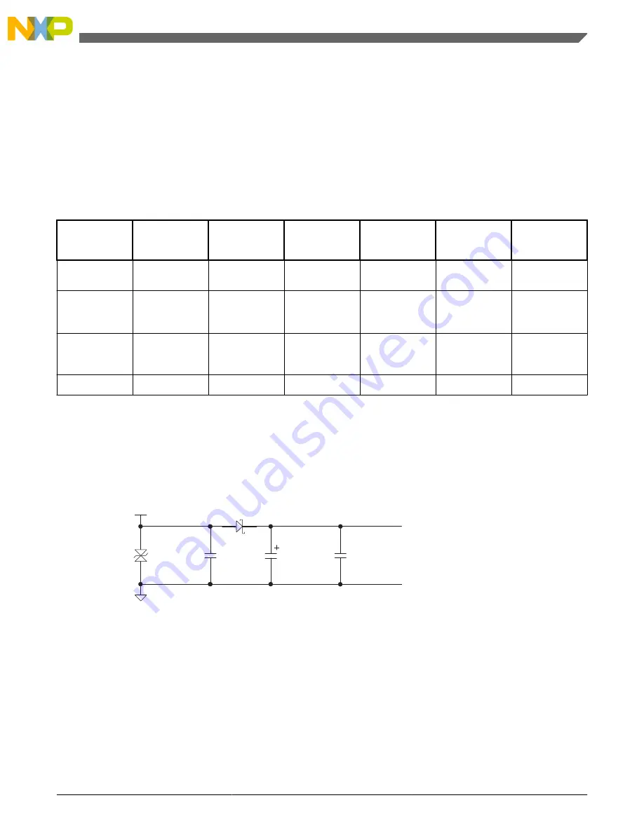
In a typical system, the battery reverse bias and over-voltage protection may be shared between all of the communication
devices in the target system.
Figure 7
shows a typical protection.
SMCJ24CA
100nF
VBAT
Protected Battery Voltage
100nF
MBRA140T3
100uF 35V
Ground Return
Figure 7. Typical protection circuit
8.1 Example RS-232 interface for LINFlex
The RS-232 (TIA/EIA-232-F) standard is a fairly common interface that was once available on nearly all computers. While
this interface is disappearing, adapters are available to allow the use of RS-232 peripherals through other interfaces, such as
USB. RS-232 was intended to be a very low-cost, low-performance interface. This interface was originally specified with
signal voltages of +12 V and –12 V typically. However, this has been lowered to a typical minimum voltage of +5 V and –5
V in recent years.
Example communication peripheral connections
Hardware Design Guide, Rev. 0, 2012
Freescale Semiconductor, Inc.
15


