


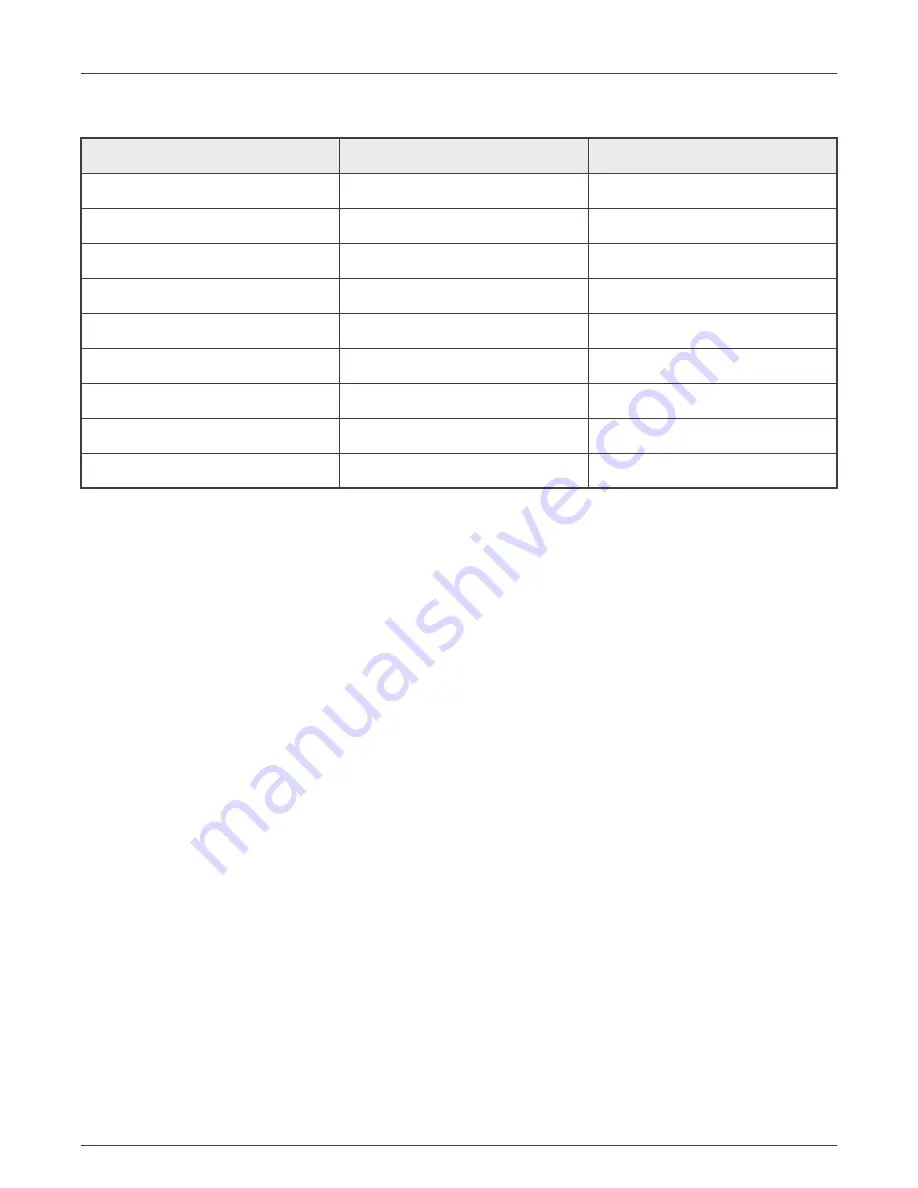
Table 4. J19, J20 Pin Definition
Num.
Net name
Description
1
NC
—
2
CAN_L
CAN transceiver low signal
3
GND
Ground
4
NC
—
5
GND
Ground
6
GND
Ground
7
CAN_H
CAN transceiver high signal
8
NC
—
9
NC
—
2.15 Audio Headset connector (J18)
The i.MX 8M LPDDR4 Plus EVK board includes one Headset (J18) for audio input/output. The connector is a 3.5 mm 4-pole CTIA
standard phone jack. The Audio CODEC used on the EVK board is Wolfson WM8960, which can support 24 bit I2S data and 48
Khz sampling rate. The connector is as shown in
Users can also populate CON1 for 8 Ω 1W per channel speaker output.
2.16 JTAG connector (J24)
The i.MX 8M Plus Applications Processor has four JTAG signals on dedicated pins, and one HW reset input signal
POR_B
.
Those signals are directly connected to the standard 10-pin 1.27 mm JTAG connector J24. The four JTAG signals used by the
processor are:
• JTAG_TCK TAP Clock
• JTAG_TMS TAP Machine State
• JTAG_TDI TAP Data In
• JTAG_TDO TAP Data Out
2.17 USB DEBUG connector (J23)
The i.MX 8M Plus Applications Processor has four independent UART Ports (UART1 – UART4). On the EVK board, UART2 is
used for Cortex-A53 core, and UART4 is used for Cortex-M7 core. A single chip USB to dual UART, JTAG and I2C is used for
UART debug and remote debug. The part number is FT4232H. The developers can download the driver from
After the driver for FT4232H is installed, the PC will enumerate four COM ports when the USB cable is plugged into J23, the third
port is used for A53 and fourth for M7 system debugging. Developers can use Putty, Tera Term, Xshell, or other terminal tools.
The required settings are as listed in
.
NXP Semiconductors
Specifications
i.MX 8M Plus LPDDR4 EVK Board Hardware User's Guide, Rev. 0, March 9, 2021
User's Guide
12 / 20