NXP Semiconductors i.MX 8M Plus LPDDR4 EVK Hardware User'S Manual Download Page 13

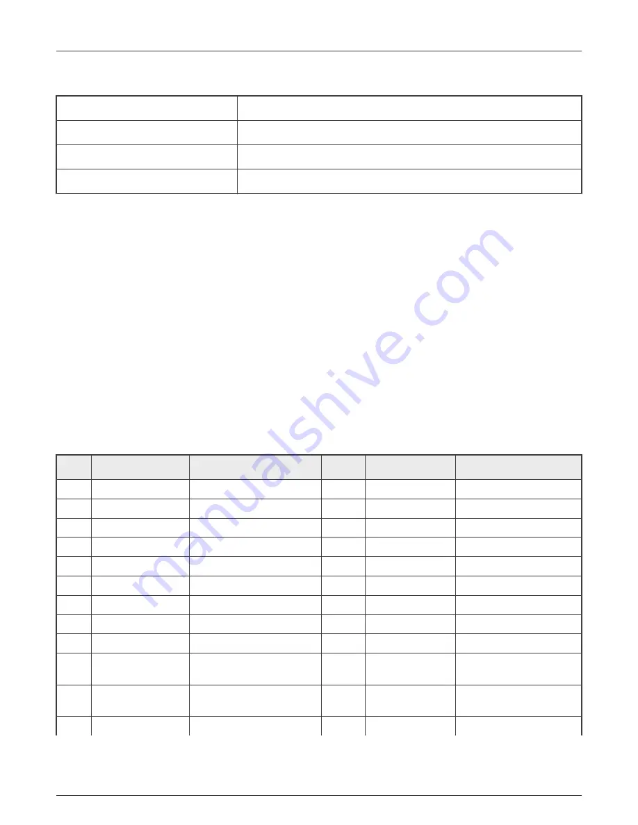
Table 5. Terminal setting parameters

Data rate

115,200 Baud

Data bits

8

Parity

None

Stop bits

1

The first and second ports of FT4232H are used for remote debug of JTAG, Bootmode, ONOFF, SYS_nRST, and Power
Measurement Board communication. Developers can load different images on PC for associated applications.
The connector is as shown in 

Figure 2

.

2.18 M.2 slot and Wi-Fi/Bluetooth module (J10)

One M.2/NGFF KEY-E slot (J10) is provided on the EVK board to support PCIE3.0, SDIO, I2S, UART, I2C, and GPIO connection.
This port can be used for Wi-Fi/Bluetooth card, NVMe PCIE SSD or 3G/4G cards. On the EVK board, Wi-Fi/Bluetooth module
Azurewave AW-CM276MA-07H (PCIE+UART) is assembled as default. It’s based on NXP 88W8997 chipset, supports Wi-Fi 5
(802.11ac) 2 × 2 Dual-Band (2.4/5 GHz), Bluetooth 5.1.
The connector is as shown in 

Figure 2

.

2.19 Expansion connector (J21)

One 40-pin dual-row Pin Header connector (J21) is provided on the EVK board to support I2S, UART, I2C, and GPIO connections.
Developers can use the header for access to various pins or to plug in accessory cards like the 8MIC-RPI-MX8.
The connector is as shown in 

Figure 2

.

Table 6. J21 pin definition

Num.

Net name

Description

Num.

Net name

Description

1

VEXT_3V3

Power Output, 3.3 V

2

VDD_5V

Power Output, 5 V

3

I2C3_SDA_3V3

I2C3 data signal

4

VDD_5V

Power Output, 5V

5

I2C3_SCL_3V3

I2C3 clock signal

6

GND

Ground

7

UART3_CTS_3V3

UART3 clear to send signal

8

UART3_TXD_3V3

UART3 transmit signal

9

GND

Ground

10

UART3_RXD_3V3

UART3 transmit signal

11

UART3_RTS_3V3

UART3 request to send signal

12

EXP_P1_0

Expansion IO signal

13

EXP_P1_1

Expansion IO signal

14

GND

Ground

15

EXP_ P1_2

Expansion IO signal

16

EXP_P1_3

Expansion IO signal

17

VEXT_3V3

Power Output, 3.3V

18

EXP_P1_4

Expansion IO signal

19

ECSPI2_MOSI_3V3

SPI2 data signal, master

output slave input

20

GND

Ground

21

ECSPI2_MISO_3V3 SPI2 data signal, master input

slave output

22

EXP_P0_7

Expansion IO signal

23

ECSPI2_SCLK_3V3

SPI2 clock signal

24

ECSPI2_SS0_3V3

SPI2 chip select signal

Table continues on the next page...

NXP Semiconductors

Specifications

i.MX 8M Plus LPDDR4 EVK Board Hardware User's Guide, Rev. 0, March 9, 2021

User's Guide

13 / 20

Summary of Contents for i.MX 8M Plus LPDDR4 EVK

Page 1: ...i MX 8M Plus LPDDR4 EVK Board Hardware User s Guide NXP Semiconductors Document identifier IMX8MPEVKHUG User s Guide Rev 0 March 9 2021...

Page 2: ...nnector J17 11 2 12 Ethernet connectors J8 J9 11 2 13 USB connectors J5 J6 J7 11 2 14 CAN Bus connectors J19 J20 11 2 15 Audio Headset connector J18 12 2 16 JTAG connector J24 12 2 17 USB DEBUG connec...

Page 3: ...Plus LPDDR4 EVK board Table 1 Board features Processor NXP Applications Processor MIMX8ML8DVNLZAA DRAM memory 6 GB LPDDR4 Micron MT53E1536M32D4DT 046 WT A Mass storage 32 GB eMMC5 1 SanDisk SDINBDG4...

Page 4: ...2 3 inch 2 3 inch 6 layer 8MPLUS BB 6 inch 8 26 inch 8 layer 1 2 Board contents The i MX 8M Plus LPDDR4 EVK contains the following items i MX 8M Plus LPDDR4 EVK board assembled by two separate boards...

Page 5: ...LPDDR4 EVK board Figure 1 describes each block in the high level block diagram of the LPDDR4 EVK board Figure 1 i MX 8M Plus LPDDR4 EVK block diagram Figure 2 and Figure 3 show the overview of the i...

Page 6: ...op view i MX 8M Plus LPDDR4 EVK board Figure 3 Back view i MX 8M Plus LPDDR4 EVK board NXP Semiconductors Specifications i MX 8M Plus LPDDR4 EVK Board Hardware User s Guide Rev 0 March 9 2021 User s G...

Page 7: ...MIPI Camera HDMI LVDS WLAN Bluetooth PCIe USB3 0 uSDHC Ethernet FlexCAN and multi sensors For more detailed information about the processor see i MX8MPLUS datasheet and reference manual 2 2 Boot mode...

Page 8: ...on the Base Board Set SW4 as 0010 to choose uSDHC3 eMMC as boot device set 0011 to choose uSDHC2 SD and set 0110 to choose QSPI Nor Set 0001 to enter USB Serial Download NAND boot is not supported on...

Page 9: ...In Figure 6 the developers can see all the voltage supplies used on the EVK board When some modules are not enabled the related power supplies might be shut down by software Table 3 lists the power r...

Page 10: ...DDR4 chips in sequential order but for ease of routing are connected as best determined by the layout and other critical traces The DRAM_VREF can be generated by i MX 8M Plus internally so it does not...

Page 11: ...DA pin on the EVK The i MX 8M LPDDR4 Plus EVK board has a Type A HDMI connector the resolution can be up to 4Kp30 The connector is as shown in Figure 2 2 12 Ethernet connectors J8 J9 The Ethernet subs...

Page 12: ...dard 10 pin 1 27 mm JTAG connector J24 The four JTAG signals used by the processor are JTAG_TCK TAP Clock JTAG_TMS TAP Machine State JTAG_TDI TAP Data In JTAG_TDO TAP Data Out 2 17 USB DEBUG connector...

Page 13: ...pers can use the header for access to various pins or to plug in accessory cards like the 8MIC RPI MX8 The connector is as shown in Figure 2 Table 6 J21 pin definition Num Net name Description Num Net...

Page 14: ...rt for some specific application development The connector is as shown in Figure 2 Table 7 J22 pin definition Num Net name Description 1 2 VEXT_3V3 Power Output 3 3 V 3 4 I2C5_SCL_3V3 I2C clock signal...

Page 15: ...l 3 3 V 26 FT_IO_06 FT4232 expander IO signal 1 8 V 27 FT_GPIO2 FT4232 IO signal 3 3 V 28 FT_IO_07 FT4232 expander IO signal 1 8 V 29 GND Ground 30 GND Ground 31 FT_GPIO3 FT4232 IO signal 3 3 V 32 FT_...

Page 16: ...outputs except NVCC_SNVS_1V8 on the EVK board The i MX 8M Plus applications processor will be immediately turned off and reinitiate a boot cycle from the OFF state 2 23 User interface LED indicators T...

Page 17: ...Figure 7 LED indicator NXP Semiconductors Specifications i MX 8M Plus LPDDR4 EVK Board Hardware User s Guide Rev 0 March 9 2021 User s Guide 17 20...

Page 18: ...67 RC74 3 49 2 5 mil 2 GND 1 Dielectric Core 0 075MM 1 1 3 97 2 95 mil 3 Signal 1 Dielectric 7628 RC49 2116 RC54 2116 RC54 7628 RC49 4 15 4 01 4 01 4 15 26 4 mil 4 Power 1 Dielectric Core 0 075MM 1 1...

Page 19: ...lectric 2116 RC58 7628 RC47 3 91 4 2 12 7 mil 6 Signal 1 Dielectric Core 0 1MM 1 1 4 13 3 94 mil 7 GND 1 Dielectric 1080 RC64 3 75 2 96 mil 8 Signal 0 5 Plating 1 31 mil Finished 62 992 6 299 6 299 mi...

Page 20: ...updates from NXP and follow up appropriately Customer shall select products with security features that best meet rules regulations and standards of the intended application and make the ultimate desi...

Reviews: