background image


Advanced Video Control Unit (AVCU) User Guide


5

     |  www.nvisinc.com


CONFIGURING THE AVCU 


AUTOMATIC VIDEO DETECTION 

Input video detection is built into the AVCU and is enabled by default.  The AVCU has circuitry 
that can detect several video input configurations.  These include the following:  
 

  VGA mono (left or right) 

  DVI mono (left or right) 

  VGA stereo 

  DVI stereo 

  Mixed stereo (using VGA and DVI video signals to achieve a stereoscopic set up). 

 
The  default  video  detection  setting  may  not  work  for  all  situations.    It  may  be  required  in  rare 
instances, with older video generators, third-party video splitters and/or VGA cables with missing 
pins, to disable the automatic detection setting. It is recommended that VGA cables with all 15 
pins be used with the AVCU.  Instructions for disabling the video detection circuit can be found 
later in this guide. 

 
NAVIGATING THE AVCU INTERFACE 

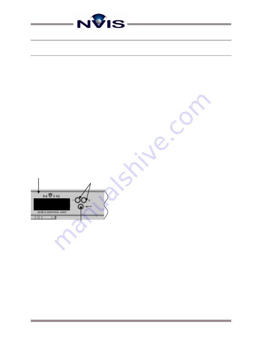
The front of the AVCU has an LCD screen that displays various settings and messages.  Next to 
the LCD reside three buttons used for navigation and toggling settings (Figure 5).  


Upon powering the AVCU and pressing the power button located on the left side of the front panel, 
the LCD will display the AVCU product name as well as the version number of the firmware. 
 
The “enter” button cycles through four information banners.  The information displayed in these 
banners  is  designed  to  help  the  user  configure  the  input  video  signals.    The  first  banner  is 
mentioned  above,  displaying  the  product  name  and  firmware  version.    The  second  banner 
displays video timing information (Figure 6 and Figure 7).  A third banner displays which various 
video inputs are detected (Figure 8).  The last banner shows the current monitor out configuration 
for a stereo setup (Figure 9). 


  LCD Control Panel      


      Display 


Left and Right     


      Selection Buttons 


Enter Button


AVCU-W 
Version 1.4 

t  

Figure 5 AVCU Navigation Buttons


Summary of Contents for AVCU

Page 1: ......

Page 2: ...nced Video Control Unit 3 Step by Step Setup Procedures 4 Configuring the AVCU 5 Automatic Video Detection 5 Navigating the AVCU Interface 5 Adjusting Brightness 6 Setting AVCU Preferences 7 Using SXP...

Page 3: ...TROL UNIT The AVCU accepts the video signal from the image generator and provides the correct sync and voltage information to the microdisplays in the head mounted display The AVCU design supports mul...

Page 4: ...ich includes the universal power supply into the AVCU and into 110 220V AC source Connect your video cable s to the computer and to the AVCU Connect an optional external monitor from the AVCU two exte...

Page 5: ...r in this guide NAVIGATING THE AVCU INTERFACE The front of the AVCU has an LCD screen that displays various settings and messages Next to the LCD reside three buttons used for navigation and toggling...

Page 6: ...n for both eyes will be displayed Figure 8 shows and example of the video detection banner In the example a DVI signal is detect on the left channel as indicated by the x Figure 8 Video Detection Disp...

Page 7: ...one by pressing buttons to scroll through the various settings You can hit the Enter button to change a setting In Figure 11 the DAC output setting is selected The pointy brackets on the first line of...

Page 8: ...nputs for analog signals If this is the case the automatic video detection circuitry will fail to detect incoming video signals To set up the video inputs correctly one of the manual analog settings w...

Page 9: ...efault two files with the hex extension are placed in the following directory folder path or similar based on your specific installation C Program Files SXprog User Code Select both the AP hex and BP...

Page 10: ...ctor on the AVCU Launch the SXprog application Before starting make sure you have the new color sequence file loaded into the following directory folder path or similar based on your specific installa...

Page 11: ...ormat you are using Pixel screen position is adjusted for standard analog video at the factory unless otherwise requested If pixel screen position is improperly adjusted horizontal wrapping can occur...

Page 12: ...in regions of the database that contain transitioning color gradients or textures with many gray levels This situation is caused by the time delay between modulating for the first and last bit of a gi...

Page 13: ...native bits per color with 4 bit dither boost Once you ve set the dithering configuration you need to go to the Sequence screen to select the appropriate color sequence for your dithering configuratio...

Page 14: ...to force the AVCU to VGA mode There are two such modes depending if you have a single input or dual Consult Configuring the AVCU for more information Digital video configuration issues should be rare...

Page 15: ...NVIS Inc 11495 Sunset Hills Road Ste 106 Reston VA 20190 www nvisinc com 571 201 8095...

Reviews: