


Advanced Video Control Unit (AVCU) User Guide
3
| www.nvisinc.com
WELCOME
Thank you for purchasing your NVIS display system. This manual documents the operation of
your Advanced Video Control Unit (AVCU). The AVCU is video interface for the following NVIS
displays:
nVisor SX60,
nVisor SX111, and
Virtual Binocular SX. There are additional
legacy systems that may use the AVCU as well, and the general operation should be the same
as explained in this manual.
The AVCU video interface accepts standard digital or analog video from a commercial PC
workstation and converts this video information into the digital signals required by the microdisplay
in your NVIS head-mounted or hand-
held display device. It’s a critical component of your overall
system and this document provides an overview of how to connect, configure, and use your NVIS
display using the AVCU.
BASIC FUNCTION OF THE ADVANCED VIDEO CONTROL UNIT
The AVCU accepts the video signal from the image generator and provides the correct sync and
voltage information to the microdisplays in the head-mounted display. The AVCU design supports
multiple product configurations and as such, accommodates single and dual video input options.
The partial optical overlap configuration of the nVisor SX111 optical system requires different
viewing frustum parameters for each eye and therefore must always operate with different LEFT
and RIGHT eye images. This is explained in more detail later in the manual.
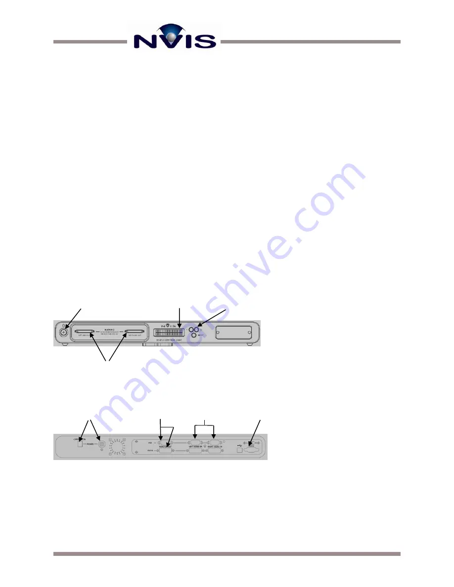
The front panel of the AVCU is shown in Figure 1.
The back panel of the AVCU is shown in Figure 2. The back panel is used to connect DC power
and the left and right input cables from a VGA video card or a DVI video card.
Power Input and Indicator
Outputs to VGA or DVI
repeater monitor
Inputs from VGA or DVI
video card
USB and RS232
Figure 1 Front Panel of the AVCU
Figure 2 Back Panel of the AVCU
LCD
Power On/Off
Selection Buttons
Left and right outputs to
the head-mounted display
Left and right outputs to
the head-mounted display


