background image

Shelf Manager ACB-VI

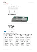
Shelf Manager Connectors

26

R1.2, March 2018

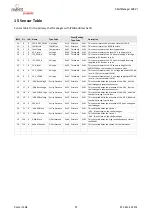
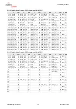
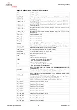
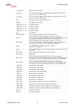
Table 8:  Backplane Signal Connector (X102) pin assignment (Radial IPMB)

Table 9:  Backplane Signal Connector (X102) pin assignment (Bused IPMB)

a

PS

b

PS

c

PS

d

PS

e

PS

f

PS

1

FT0_PRES#

A

UART0_TXD

A

UART1_TXD

A

FT2_PRES#

A

INT#

A

GND

C

2

FT1_PRES#

A

UART0_DTR

A

Pres_GND

A

AUX_PRES#

A

UART0_DSR

A

C

3

UART0_CD

A

UART0_RTS

A

UART1_RXD

A

HA0

A

UART0_CTS

A

GND

C

4

UART0_RXD

A

I2C_SDA_CH1

A

ACTIVE

A

I2C_SDA_CH0

A

GND

A

C

5

I2C_SCL_CH1

A

I2C_SCL_CH0

A

UART0_RI

A

GND

A

I2C_SDA_CH3

A

GND

C

6

A

ETH0_TX-

A

GND

B

USB1_DP

A

USB1_DM

A

C

7

A

ETH0_RX-

A

GND

B

USB0_DP

A

USB0_DM

A

GND

C

8

I2C_SDA_CH4

A

I2C_SCL_CH4

A

I2C_SCL_CH3

A

I2C_SCL_CH2

A

I2C_PWR_B

A

C

9

IPMB_SCL_B15

A

IPMB_SDA_B15

A

IPMB_SCL_A15

A

IPMB_SDA_A15

A

I2C_SDA_CH2

A

GND

C

10

IPMB_SDA_B16

A

IPMB_SCL_B16

A

IPMB_SDA_A16

A

IPMB_SCL_A16

A

I2C_PWR_A

A

11

IPMB_SDA_A3

A

IPMB_SDA_B3

A

IPMB_SCL_B3

A

IPMB_SDA_B8

A

IPMB_SCL_B8

A

GND

12

IPMB_SCL_A3

A

IPMB_SDA_A5

A

IPMB_SCL_A5

A

IPMB_SDA_A8

A

IPMB_SCL_A8

A

13

IPMB_SDA_A1

A

IPMB_SDA_B7

A

IPMB_SCL_A1

A

IPMB_SDA_A10

A

IPMB_SCL_A10

A

GND

14

IPMB_SCL_B7

A

IPMB_SDA_A7

A

IPMB_SCL_A7

A

IPMB_SDA_A6

A

IPMB_SCL_A6

A

C

15

IPMB_SDA_A9

A

IPMB_SDA_B14

A

IPMB_SCL_B14

A

IPMB_SDA_B10

A

IPMB_SCL_B10

A

GND

C

16

IPMB_SCL_A9

A

IPMB_SDA_A4

A

IPMB_SCL_A4

A

IPMB_SDA_B6

A

IPMB_SCL_B6

A

C

17

CROSS_SDA_B

A

IPMB_SDA_B11

A

IPMB_SCL_B11

A

IPMB_SDA_B4

A

IPMB_SCL_B4

A

GND

C

18

CROSS_SCL_B

A

IPMB_SDA_A11

A

IPMB_SCL_A11

A

IPMB_SDA_A14

A

IPMB_SCL_A14

A

C

19

IPMB_SDA_A13

A

IPMB_SCL_A13

A

IPMB_SCL_B12

A

IPMB_SDA_B12

A

IPMB_SDA_B9

A

GND

C

20

IPMB_SDA_B1

A

IPMB_SCL_B1

A

CROSS_SCL_A

A

CROSS_SDA_A

A

IPMB_SCL_B9

A

C

21

IPMB_SDA_B13

A

IPMB_SDA_B5

A

IPMB_SCL_B5

A

IPMB_SDA_B2

A

IPMB_SCL_B2

A

GND

C

22

IPMB_SCL_B13

A

IPMB_SDA_A12

A

IPMB_SCL_A12

A

IPMB_SDA_A2

A

IPMB_SCL_A2

A

C

a

PS

b

PS

c

PS

d

PS

e

PS

f

PS

1

FT0_PRES#

A

UART0_TXD

A

UART1_TXD

A

FT2_PRES#

A

INT#

A

GND

C

2

FT1_PRES#

A

UART0_DTR

A

Pres_GND

A

AUX_PRES#

A

UART0_DSR

A

C

3

UART0_CD

A

UART0_RTS

A

UART1_RXD

A

HA0

A

UART0_CTS

A

GND

C

4

UART0_RXD

A

I2C_SDA_CH1

A

ACTIVE

A

I2C_SDA_CH0

A

GND

A

C

5

I2C_SCL_CH1

A

I2C_SCL_CH0

A

UART0_RI

A

GND

A

I2C_SDA_CH3

A

GND

C

6

A

ETH0_TX-

A

GND

B

USB1_DP

A

USB1_DM

A

C

7

A

ETH0_RX-

A

GND

B

USB0_DP

A

USB0_DM

A

GND

C

8

I2C_SDA_CH4

A

I2C_SCL_CH4

A

I2C_SCL_CH3

A

I2C_SCL_CH2

A

I2C_PWR_B

A

C

9

A

A

A

A

I2C_SDA_CH2

A

GND

C

10

A

A

A

A

I2C_PWR_A

A

11

A

A

A

A

A

GND

12

A

A

A

A

A

13

A

A

A

A

A

GND

14

A

A

A

A

A

C

15

A

IPMB_SDA_B

A

IPMB_SCL_B

A

A

A

GND

C

16

A

A

A

A

A

C

17

A

A

A

A

A

GND

C

18

A

A

A

IPMB_SDA_A

A

IPMB_SCL_A

A

C

19

A

A

A

I

A

A

GND

C

20

A

A

A

A

C

21

A

A

A

A

A

GND

C

22

A

A

A

A

A

C

Summary of Contents for 21990-401

Page 1: ...Schroff Shelf Manager ACB VI User s Manual Product Numbers 21990 401 21990 402 Doc No 63972 331_R1 2 March 2018 ...

Page 2: ...ported by certified Quality Management System to EN ISO 9001 2000 The company cannot accept any liability for errors or misprints The company reserves the right to amendments of technical specifications due to further development and improvement of products Copyright 2018 All rights and technical modifications reserved R1 0 March 2018 rebranded ...

Page 3: ...er 21990 402 8 4 RS 232 Interfaces 9 4 1 Serial Console Cables 10 5 Ethernet Interface 10 6 Shelf Manager and Shelf Alarm Panel 11 7 Master Only I C Bus 12 8 Power Supply 13 8 0 1 DC DC Converter 13 8 0 2 Input Fuses 14 8 0 3 Voltage and Fuse Monitoring 14 9 Fan Control 15 9 1 Schroff Fan Trays 16 9 1 1 Control characteristics examples 16 10 Hardware Address 17 11 RESET 17 11 1 Reset Input Output ...

Page 4: ...Shelf Manager ACB VI II R1 2 March 2018 ...

Page 5: ...nal electrical codes For additional information about this equipment see the PICMG 3 0 Specification www picmg org Hazardous voltage This is the electrical hazard symbol It indicates that there are dangerous voltages inside the Shelf Caution This is the user caution symbol It indicates a condition where damage of the equipment or injury of the service personnel could occur To reduce the risk of da...

Page 6: ...og with Two Wire Interface 1 4 Terms and Acronyms Table 1 Terms and Acronyms Term Definition ATCA Advanced Telecom Computing Architecture Backplane Passive circuit board providing the connectors for the front boards Power distribution management and auxiliary signal connections are supported CDM Chassis FRU Data Module ECN Engineering Change Notice ESD Electrostatic Discharge ETSI European Telecom...

Page 7: ...t aspects of Shelf management based on the ShMM 700R These facilities include I C based hardware monitoring control and GPIO expander devices The ACB VI also provides the Fan Controller for up to 9 Fans and individual Ethernet connections to both Base Hubs ShMC cross connect The Shelf Manager communicates inside the Shelf with IPM controllers over the Intelligent Platform Management Bus IPMB The S...

Page 8: ...I Safety 4 R1 2 March 2018 Figure 1 Schroff Shelf Manager ACB VI 12714825 1 Extraction handle 5 Backplane Connector X100 2 ShMM 700R 6 Backplane Connector X102 3 RTC backup capacitor 7 Fixing screw 4 ACB VI Carrier Board ...

Page 9: ...ge monitoring On board temperature monitoring Detection of hardware address with parity Injector Ejector handle with Hot Swap switch Hot swap LED Capacitor for the ShMM 700R RTC Hardware redundancy interface with dedicated communication paths between dual Shelf Managers for redundant operation Interrupt requests for the ShMM 700R generated by on board and off board devices Status indication for im...

Page 10: ... Service OOS 3 ETH 0 Link Activity LED yellow On Link Off No Link Blinking Activity 8 Shelf Manager Status LED green Solid Green in Service active Shelf Manager Blinking in Service Backup Shelf Manager 4 ETH 1 Link Activity LED yellow On Link Off No Link Blinking Activity 9 Hot Swap Switch Activated by extraction handle 5 Hot Swap LED blue Solid Blue ready to remove Blinking Hot Swap is requested ...

Page 11: ...FRU Presence and Fuse Monitoring 0x25 ADT7490 I2C_PWR_A_MON Fan 7 9 Tacho ADT7490 I2C_PWR_B_MON PWM Voltage Fan 1 3 Tacho ADT7490 0x2C 0x2E 0x2D PCA9554 0x23 Hardware Address HA FRU Presence Fuse Mon MRST_IN ETH0 ETH1 I2C0 I2C1 I2C2 I2C3 I2C4 I2C_LOCAL RTC ETH0 ETH1 RESET Red Status Green Status Blue Hot Swap Hot Swap HANDLE_CLOSED BLUE_LED STATUS_LED_GREEN STATUS_LED_RED ETH1_ACT ETH0_ACT 20 V Po...

Page 12: ...00R is used to switch on off the pull up resistors of the IPMBs Figure 4 Block diagram bused IPMB 3 2 Radial IPMB Interface Product Number 21990 402 Radial IPMB is implemented by 2 FPGAs connected to the Serial Peripheral Interfaces SPI on the ShMM700R Figure 5 Block diagram radial IPMB 7 R Enable Ready Enable Ready LTC 4300 LTC 4300 ShMM 700R SPI_A SPI_B 3 3 V FPGA 1 IBMB_A 1 Radial_B_Enable Radi...

Page 13: ... backplane connector to the SAP The SAP provides two 8 pin RJ45 modular receptacles for the serial interfaces of both Shelf Managers The second serial interface does not provide modem control signals These signals are also routed to the backplane connector but not used in the Schroff ATCA Shelves Figure 6 RS 232 Serial Ports ShMM 700R Connector Backplane Connector UART0 UART1 ACB VI ShMM 700R UART...

Page 14: ... Telecommunication Network Circuit that leaves the building The ETH0 interface of the shelf manager can manually be switched between the front panel RJ45 connector Front position of the rocker switches and the backplane connector going to the hub board base interface Back position of the rocker switches The ATCA specification requires a base channel interface between the shelf manager and the Hub ...

Page 15: ...he Chassis that is easy to reach and operate by service personnel The figure below shows the interconnection between the Shelf Managers and the SAP Please note that the design of the SAP is Shelf dependent Please see your Shelf User Manual for the actual SAP implementation in your Shelf Please see chapter Telco Alarms for detailed information concerning the Telco Alarm interface and the user defin...

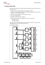
Page 16: ...re SEEPROM Shelf Manager FRU information PCA9543 This 2 channel switch divides the I C bus 3 into 2 channels to the SAP Channel 0 the PEMs Channel 4 The Active signal of the ShMM 700R is used to enable the LTC4300 so that only the active Shelf Manager has access to the Shelf I C bus devices Figure 10 Master Only I2C bus ShMM 700 I2C0 I2C1 I2C2 I2C3 I2C4 local LTC4300A 1 LTC4300A 1 LTC4300A 1 LTC43...

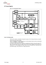
Page 17: ...2C_PWR_A and I2C_PWR_B are routed to the backplane connector and used to power I C devices on FRUs like the Fan Tray PEM or SAP If one of these voltages is short circuited in a chassis FRU or on the backplane the short circuit current is limited to 700 900 mA so that the Shelf Manager and the FRUs are still fully operational Backplane Connector 5 V for ShMM 700R I2C_PWR_A I2C_PWR_B FAN_24V Linear ...

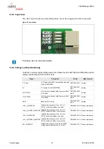
Page 18: ...oing to Shelf I C devices ADT7490 0x2D pin 20 Analog I2C_PWR_B 3 6 V supply redundant path B going to Shelf I C devices ADT7490 0x2E pin 20 Analog VBAT Backup CAP voltage ADT7490 0x2E pin 21 Analog 48V_A_MONITOR Indicates the presence of the 48 V_A VRTN_A at the backplane connector PCA9555 I O 0 5 Presence Absence 48V_A_FUSED_MONITOR Indicates the presence of the 48 V_A VRTN_A after the ACB VI s m...

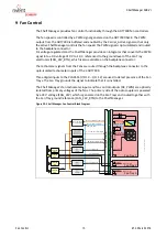
Page 19: ...tal inputs to the PCA9555 I O 1 0 I O 1 2 are used to detect presence of the Fan Trays The Fan Tray grounds the signal to indicate that it is installed The Shelf Manager s fan tachometer inputs and fan control outputs DC PWM are optically isolated from primary voltages of the fans The primary side of the opto couplers is powered by a 24 V voltage FAN_24V which is generated on the Fan Trays and rou...

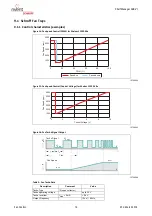
Page 20: ...cho Signal Output Table 2 Fan Tacho Data 12706964 1000 0 2000 3000 4000 5000 0 20 40 60 80 100 PWM Fan Speed rpm Speed up Speed down 12706965 1000 0 2000 3000 4000 5000 6000 0 2 4 6 8 10 Control Voltage V Fan Speed rpm 12706966 Tacho Signal 1 rev t t 1 2 Fan Speed US Low US High n min n max n US t t Description Comment Value Tacho Type 2 open collector Tacho operating voltage up to 30 V Tacho leve...

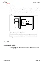
Page 21: ...e determines the hardware address by reading the input port register of the PCA9554 at address 0x23 Figure 17 Table 3 Shelf Manager Hardware and IPMB Addresses 11 RESET 11 1 Reset Input Output The ACB VI provides a RESET push button on the front panel It is connected to the ShMM 700 s MRST_IN signal 8 bit GPIO port PCA9554 0x23 ACB VI Carrier Board Backplane Connector I2C4 local ShMM 700R ShMM 700...

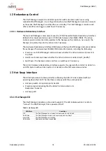
Page 22: ...e each Shelf Manager instance knows whether the other instance is present in the shelf Health each instance knows whether the other instance considers itself healthy Switchover the backup instance can force a switchover if necessary The ACB VI Hardware Redundancy Interface supports the upgrade from ACB V to ACB VI in an ATCA System without interruption For details see the firmware release notes 13...

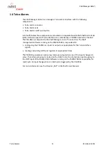
Page 23: ...r via an I C connection The Shelf management software running on the ShMM 700R is responsible for configuring the PCA9555 as inputs or outputs as appropriate for the Telco interface signals reading and writing GPIO port registers at appropriate times The PCA9555 generates an active low interrupt output when one of the inputs changes its value That interrupt output is routed on the ACB VI onto the ...

Page 24: ... 1V5_FPGAB Voltage 0x02 Threshold 0x01 This sensor measures the 1 5 V voltage supplied to FPGAB in volts Only with radial IPMB 10 16 0 48A Bus voltage Entity Presence 0x25 Discrete 0x6f This sensor indicates the presence of the 48 V_A at the shelf manager backplane connector 10 17 0 48B Bus voltage Entity Presence 0x25 Discrete 0x6f This sensor indicates the presence of the 48 V_B at the shelf man...

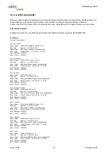
Page 25: ...008000 Entry Point 40008000 Current RFS Image Name 63998 53456 RFS 3 4 0 Created Wed Jul 2 20 05 47 2014 Image Type ARM Linux RAMDisk Image gzip compressed Data Size 2573577 Bytes 2513 26 kB 2 45 MB Load Address 00000000 Entry Point 00000000 Current Application Image Name 63998 53456 APP 3 4 0 Created Wed Jul 2 20 05 46 2014 Image Type ARM Linux Filesystem Image gzip compressed Data Size 2432907 B...

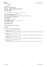
Page 26: ...ooling_acb so Version 3 4 0 1 Carrier Product ID 21990401 Chassis Product ID 11596150 Command clia ipmc Displays all IPMC controller in the chassis clia ipmc Pigeon Point Shelf Manager Command Line Interpreter 10 Entity 0xf0 0x60 Maximum FRU device ID 0x00 PICMG Version 2 3 Hot Swap State M4 Active Previous M3 Activation In Process Last State Change Cause Normal State Change 0x0 12 Entity 0xf0 0x6...

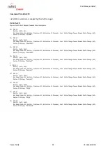
Page 27: ... M4 Active Previous M3 Activation In Process Last State Change Cause Normal State Change 0x0 Device ID String FanTray0 2 0 FRU 4 Entity 0x1e 0x61 Hot Swap State M4 Active Previous M3 Activation In Process Last State Change Cause Normal State Change 0x0 Device ID String FanTray1 20 FRU 5 Entity 0x1e 0x62 Hot Swap State M4 Active Previous M3 Activation In Process Last State Change Cause Normal State...

Page 28: ...5 Dynamic minimum fan level 3 20 FRU 3 Current Level 4 Minimum Speed Level 1 Maximum Speed Level 15 Dynamic minimum fan level 3 Command clia shmstatus v Displays the status of the ACB VI shelf manager clia shmstatus v Pigeon Point Shelf Manager Command Line Interpreter Host Active Ready For Operation Yes Detailed State Flags Shelf FRU Found Backup Healthy Initial Update Sent RMCP Up Shelf FRU Proc...

Page 29: ...ng PS is the length of the Pins of the connector at the Backplane not at the Shelf manager a PS b PS c PS d PS e PS 1 48 V_A B VRTN_A B NC B 48 V_B B VRTN_B B 2 3 SHELF_GND B SHELF_GND B SHELF_GND B SHELF_GND B SHELF_GND B 4 5 FAN_TACH0 A FAN_TACH1 A FAN_TACH2 A FAN_TACH3 A FAN_TACH4 A 6 FAN_TACH5 A FAN_TACH6 A FAN_TACH7 A FAN_TACH8 A PWM_C A 7 FAN_SPEED A NC A FAN_24V A FAN_24V_RTN A PWM_E A 8 9 ...

Page 30: ...MB_SCL_B14 A IPMB_SDA_B10 A IPMB_SCL_B10 A GND C 16 IPMB_SCL_A9 A IPMB_SDA_A4 A IPMB_SCL_A4 A IPMB_SDA_B6 A IPMB_SCL_B6 A C 17 CROSS_SDA_B A IPMB_SDA_B11 A IPMB_SCL_B11 A IPMB_SDA_B4 A IPMB_SCL_B4 A GND C 18 CROSS_SCL_B A IPMB_SDA_A11 A IPMB_SCL_A11 A IPMB_SDA_A14 A IPMB_SCL_A14 A C 19 IPMB_SDA_A13 A IPMB_SCL_A13 A IPMB_SCL_B12 A IPMB_SDA_B12 A IPMB_SDA_B9 A GND C 20 IPMB_SDA_B1 A IPMB_SCL_B1 A CR...

Page 31: ...t grounded on Fan Tray when present FAN_SPEED DC for Fan Speed Control 0 V to 10 V 10 mA FAN_TACH 0 8 Tachometer signals from Fan Trays GND logic ground HA 0 Hardware address of Shelf Manager grounded Shelf Manager IPMI address is 0x10 open Shelf Manager IPMI address is 0x12 HA7 Hardware address of Shelf Manager grounded Shelf Manager IPMI address is 0x10 open Shelf Manager IPMI address is 0x12 HL...

Page 32: ... Imax 2 mA PWM_E Opto isolated PWM signal for fan speed control emitter connected to FAN_24V_RTN on Backplane SAP_PRES Presence signal of SAP Grounded on SAP when present SHELF_GND Shelf Ground SWR_Input ACB VI Only used for transition from ACB V to ACB VI in a live chassis Formerly used on the ACB V Switchover signal from the other Shelf Manager proprie tary signal cross connected on Backplane to...

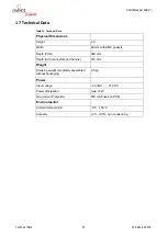
Page 33: ...Width 20 mm with EMC gaskets Depth PCB 280 mm Depth with connectors and handle 310 mm Weight Shipping weight completely assembled without packaging 0 6 kg Power Input voltage 40 VDC 72 VDC Power dissipation max 10 W Overcurrent Protection 500 mA Fuses on PCB Environmental Ambient temperature 5 C 55 C Humidity 5 85 non condensing ...

Page 34: ...Shelf Manager ACB VI Technical Data 30 R1 2 March 2018 ...

Page 35: ......

Page 36: ...Schroff GmbH Langenalber Str 96 100 75334 Straubenhardt Germany Tel 49 7082 794 0 Fax 49 7082 794 200 ...

Reviews: