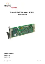
Shelf Manager ACB-VI
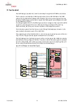
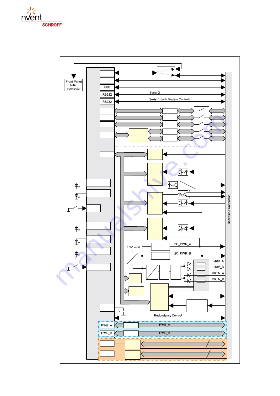
ACB-VI Block Diagram
7
R1.2, March 2018
2 ACB-VI Block Diagram
Figure 3: ACB-VI Block Diagram
LM75
0x4F
0x57
SEEPROM
ShMM-700R
Fan 4-6 Tacho
DC Fan Control
PWM Fan Control
User selectable by switch
CH1
LTC4300
CH1
CH2
LTC4300
CH3
LTC4300
CH40
LTC4300
CH4
CH2
CH3
LTC4300
CH0
CH1
CH4
CH2
CH3
CH0
CH4
CH0
PCA9543
2 Channel
I2C Switch
0x70
Hot
Swap
EMI
Filter
48 V
3.6 V
Overcurrent
Protection
Overcurrent
Protection
PCA9555
FRU
Presence
and Fuse
Monitoring
0x25
ADT7490
I2C_PWR_A_MON
Fan 7-9 Tacho
ADT7490
I2C_PWR_B_MON
PWM
Voltage
Fan 1-3 Tacho
ADT7490
0x2C
0x2E
0x2D
PCA9554
0x23
Hardware Address (HA)
FRU Presence
Fuse Mon.
MRST_IN
ETH0
ETH1
I2C0
I2C1
I2C2
I2C3
I2C4
I2C_LOCAL
RTC
ETH0
ETH1
RESET
Red
Status
Green
Status
Blue
Hot Swap
Hot Swap
HANDLE_CLOSED
BLUE_LED
STATUS_LED_GREEN
STATUS_LED_RED
ETH1_ACT
ETH0_ACT
20 V Power-
Supply for
Opto-couplers
24 VDC
generated
on Fan Trays
20 V_MON
LTC4300
LTC4300
SPI_A
FPGA 1
FPGA 2
IPMB_A radial
16
IPMB_B radial
Assembly Option bussed IPMB
Assembly Option radial IPMB
16
3.3 V
3.6 V
SPI_B
Cross_A
Cross_B
Redundancy Data

