14
10.
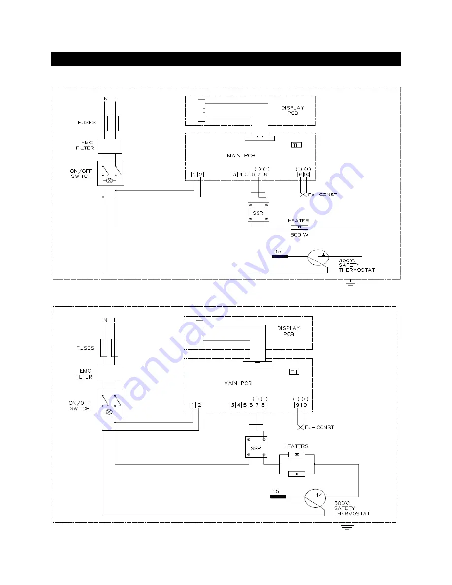
ELECTRICAL CIRCUIT DIAGRAM
10.1.
ELECTRICAL CIRCUIT DIAGRAM FOR EN 032
10.2.
ELECTRICAL CIRCUIT DIAGRAM FOR EN 055 AND EN 120
HEATERS: EN 055 2 x 700 W EN 120 2 x 800 W
Page 1: ...N VE SANAY MALZEMELER MALAT VE T CARET A EN 032 EN 055 EN 120 INCUBATORS INSTRUCTION MANUAL Z14 K25 230 Rev No 03 Rev Date 01 2016...
Page 2: ...e damaged instrument 4 do not operate the instrument with a damaged cable 5 do not move the instrument during operation In case of a problem contact your N ve agent for an authorized service or mainte...
Page 3: ...nditions use of the product in non standard environmental conditions including but not limited to failure to meet requirements of ambient temperature lubrication humidity or magnetic field influences...
Page 4: ...UNPACKING 8 5 4 MAINS SUPPLY 8 5 5 POSITIONING 8 5 6 GENERAL PRESENTATION 9 5 7 CONTROL PANEL 10 5 8 PRIOR TO OPERATION 10 6 OPERATING PRINCIPLES 11 6 2 COMPLETION OF THE WORK 12 7 PERIODIC MAINTENANC...
Page 5: ...natural air circulation Stable and homogeneous temperature in the useful volume is provided by means of the forced air circulation through the stainless steel heaters placed onto the three outer surfa...
Page 6: ...ard maximum pcs 2 6 2 7 2 10 Power Consumption 300 W 350 W 400 W Power Supply 230 V 50 60 Hz Internal Material Stainless Steel External Material Epoxy polyester painted steel Internal Dimensions W x D...
Page 7: ...not destroy the structure of the samples Liquids are not heated in sealed containers The boiling points of the samples should be higher than the set temperature Liquids which may expand during heatin...
Page 8: ...h the instrument please check them 1 ea user s manual and warranty 1 ea electrical connection cable 2 ea shelves 4 ea shelf carriers 5 4 MAINS SUPPLY The instrument requires 230V 50 60 Hz Please make...
Page 9: ...pace between the equipment and wall 5 6 GENERAL PRESENTATION Figure 1 VENTILATION ADJUSTMENT BUTTON DISPLAY AND CONTROL PANEL DOOR HANDLE PLASTIC PADS ON OFF SWITCH FUSE HOLDER AND SUPPLY INLET VENTIL...
Page 10: ...Temperature Value Increase and Decrease Keys These keys are used to increase or decrease the values on the temperature display 7 Time Set Key This key is pushed to set the time 1 minute 99 9 hours an...
Page 11: ...key t n will appear on the temperature display Set the time value by pushing the value increase and decrease keys on the time adjustment side 1 minute to 99 9 hours Hold Push the time set key again t...
Page 12: ...maintenance 7 2 CLEANING Clean the incubator and at room temperature after disconnecting the power cable Clean the incubator with a wet cloth to remove dirt and dust Use liquid detergent to remove tou...
Page 13: ...properly The installation of the plug is not defective The mains supply is present If the incubator does not heat check the followings The program is started The safety thermostat value is adjusted hi...
Page 14: ...14 10 ELECTRICAL CIRCUIT DIAGRAM 10 1 ELECTRICAL CIRCUIT DIAGRAM FOR EN 032 10 2 ELECTRICAL CIRCUIT DIAGRAM FOR EN 055 AND EN 120 HEATERS EN 055 2 x 700 W EN 120 2 x 800 W...