background image


Page 

34

 of 

87


301006_R00_IT


7.1 

Description of the Machine 

Machine  MANTA  COMPAT  200-250-300  is  an  electrical  sawing  machine that  allows  the  cut  of  each 
stony material for the construction industry. 
The  main  feature  that  distinguishes  the  MANTA  COMPAT  200-250-300  machine  lies  in  the 
affordability, versatility, simplicity and, at the same time, robustness. 
Suitable for both small workshop and large industry. 
The sawing machine MANTA COMPAT 200-250-300 is available in two versions: 
1) Manual version LX 
2) Semi-automatic version SA. 
The cutting of the material takes place by:  
 

1) Positioning the workpiece on the work surface manually by the operator. 


2)  Longitudinal  movement  of  the  cutting  head  (X-axis)  by  the  operator  by  means  of  belt 


transmission  actuated  by  a  mechanical  hand  wheel  in  the  LX  manual  version,  and  using 


instead a gear motor with electronic speed variator for the semi-automatic SA version. 


3)  Adjustment  the  cutting  height  (Z-axis)  by  hand  wheel  for  LX  manual version,  powered  by 


geared motor for semi-automatic SA version. 


4)  The  two  motorized  movements  in  the  semi-automatic  version  are  executed  with  a  single 


control device (joystick) by the operator on the switchboard. 


5) The piece remains fixed, the tool is moving during cutting. 

For these unique features, the machine takes the name of "bridge saw." 
Possibility of inclination of the head for cuts from 90 ° to 45 ° by moving the entire electric motor unit 
by means of a lever placed on the shoulders. 
Cutting  takes  place  by  means  of  a  water  recirculating  cooling  system  powered  by  electric  pumps 
submerged in the tub formed directly on the machine base. 
The structure and the base is made of painted steel, the work bench is made of galvanized steel. The 
cutter is raised on fixed angular legs with the possibility of being dismantled. 
The machine must be moved and raised exclusively with lifting equipment as described in Chapter 8 
of the manual. 

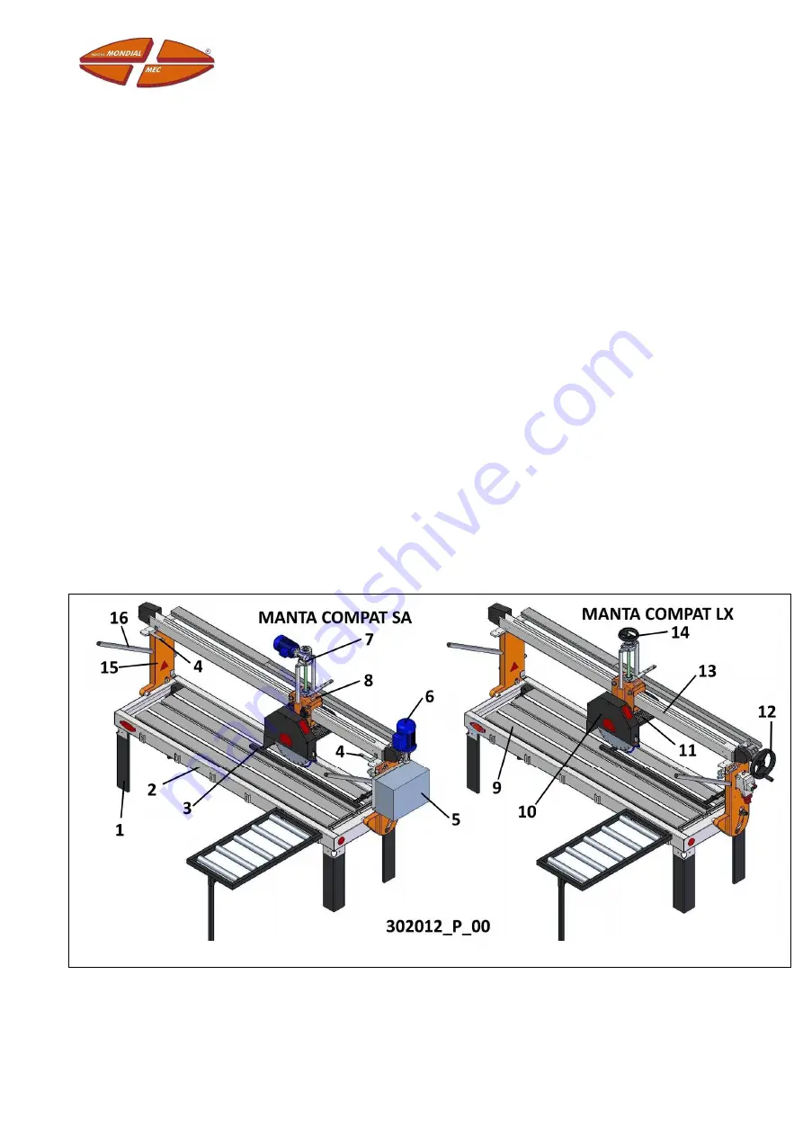
7.1.1  Composition of the Machine 

Machines are composed of the following units 


Image 3 Machine Units


Summary of Contents for MANTA COMPAT 200 LX

Page 1: ...ORIGINAL INSTRUCTIONS ENGLISH NUOVA MONDIAL MEC Srl Bridge Saw Model ________________________ Serial No ____________________ Construction Year __________ User Instructions and Maintenance Manual ...

Page 2: ...hnical Data 12 3 Warranty and Customer Service 13 3 1 Warranty 14 3 2 Customer Service 15 4 Main Information 16 4 1 Manufacturer s Details 17 4 2 Marking 17 4 2 1 Position of the Machine Plate 18 4 3 Conformity Declaration 19 5 Main Safety Regulations 20 5 1 Main Safety Warnings 21 5 2 Types of Operators and Skill Levels 21 5 2 1 Main precautionary Measures of the Machine 22 5 3 Safety Warnings fo...

Page 3: ...ions 38 8 Transportation and Storage 39 8 1 Safety Requirements for Handling 40 8 2 Description of the Packaging 40 8 3 Storage 41 8 4 Transportation Modes 42 8 4 1 Safety Requirements 42 8 4 2 Lifting Handling the Machine 42 8 4 3 The machine can be lifted only with lifting equipment e g with forklift or crane 42 8 4 4 42 8 4 5 Lifting Handling with Lifting Equipment 43 8 5 Preliminary Checks 44 ...

Page 4: ...d Functioning 56 10 5 1 Selection and Installation of Tools 57 10 5 2 Removal and Assembly Tools 57 10 5 3 Filling of the Tub with Coolant Water 58 10 5 4 Emptying the Tub 58 10 5 5 Disk Cutting Height Positioning 59 10 5 6 Disk Positioning for inclined cut at 45 59 10 5 7 PREPARATION AND COMMISSIONING 60 10 5 8 Operating Modes 60 10 5 9 Commissioning 60 10 5 10 Unloaded Machine Testing 63 10 5 11...

Page 5: ... toothed belt 70 11 4 3 Adjustment of the head wheels 71 11 4 4 Cleaning 72 11 5 Shutting down Inactivity of the Machine 72 11 6 Maintenance Register 72 11 7 Diagnostics and Troubleshooting 73 11 8 Assistance Service 74 12 Parts and Accessories 75 12 2 Parts 76 12 2 1 How to Order Spare Parts 76 12 3 Order References 76 ...

Page 6: ...6 1003_R00_IT 1 Document Revision Revision Index Revision Description Revision Date Revisor Initials 00 First Issue 01 11 2013 MB ...

Page 7: ...3004_R00_IT Pagina 7 di 87 2 Information and Management of the Document Revision Index Revision Description Revision Date Revisor Initials 00 First Issue 01 11 2013 MB ...

Page 8: ...ress written consent of the Manufacturer The Manufacturer reserves the right to change the project and to make marketable improvements without notifying customers who already have similar models The provided documentation is made as follows Instructions and Maintenance Manual Attachments 2 1 Purpose of the User Instructions and Maintenance Manual In order to safeguard the operator safety and avoid...

Page 9: ...y must be dry well known to the operators Instructions should be used with care and the Binding must be kept in its original condition that means how it appeared when delivered with the machine 2 3 How to read the User Instructions and Maintenance Manual The Instructions are formed only by the chapters relative to the supplied machine and the functional units composing it except some differences a...

Page 10: ... following symbols CAUTION DANGER This symbol indicates dangers that must be carefully considered to avoid serious personal injuries WARNING CAUTION This symbol indicates procedures and actions to be taken in order to prevent damage to property NOTE INFORMATION This symbol is used to indicate points of particular importance that should not be neglected Table 1 Typographic Conventions Table 2 Other...

Page 11: ...er a suitable training course for initial use that means to know how to drive the machine how to load and unload the material used during working process Maintenance Engineer Technician authorized trained and chosen among the ones who have the necessary skills to make interventions of routine and extraordinary maintenance on the machine Therefore he must know precise information with particular sk...

Page 12: ...ed by the operator Semi automatic Mode Working Mode of the machine not requiring continuous presence of the operator during its activity after starting only loading unloading operations of the material on the machine are excluded 2 7 1 Conventional Symbols Machine Technical Data The manufacturer identifies the technical features of his machines through typographic conventions which will be mention...

Page 13: ...3005_R00_IT Pagina 13 di 87 3 Warranty and Customer Service Revision Index Revision Description Revision Date Revisor Initials 00 First Issue 01 11 2013 MB ...

Page 14: ...ssed insufficient or wrong maintenance are excluded as well as the ones caused by lack of skill improper use use not allowed or not expected by changes or repairs not authorized by tampering or intervention on the machine effected by not qualified staff and not complying with prescriptions provided by the Manufacturer Component Replacement is granted for free if effected by the reseller after the ...

Page 15: ...ssistance concerning the machine it is necessary to indicate all data reported on the identification plate the approximate working hours and the kind of defect encountered For every need refer to the Customer Service of the Manufacturer Nuova Mondial Mec Srl Via la pastora 82 47853 Cerasolo di Coriano Rimini Italy 39 0541 759688 39 0541 756238 info nuovamondialmec com You are suggested to carefull...

Page 16: ...Pagina 16 di 87 3006_R00_IT 4 Main Information Revision Index Revision Description Revision Date Revisor Initials 00 First Issue 01 11 2013 MB ...

Page 17: ...by the manufacturer as means of product identification On the plate the identification details of the machine and main technical data useful for connection are reported Other technical information concerning the mechanical features necessary to the operators charged with maintenance and repair are indicated in the warning symbols on the machine besides this instructions manual Data indicated on th...

Page 18: ...8 Short Circuit Current kA RMS Sym 9 Serial No 10 Construction Year 11 Rated Power of Absorption 12 Rated Voltage of Power Supply 13 Rated Frequency 14 Protection Degree IP 15 Pneumatic Supply bar only cutting docking saws where a pneumatic system is present Picture 3 Data on the Machine Plate 4 2 1 Position of the Machine Plate The nameplate is located on the electrical panel cover ...

Page 19: ... related to electromagnetic compatibility The conjecture of conformity to the machine is given also through applicable parts of the regulations type A and B harmonized to the declared directives The conjecture of conformity where applicable is moreover given by means of regulations type C used by the manufacturer in case they are harmonized within the meaning of Machine Directives All references a...

Page 20: ...Pagina 20 di 87 3007_R00_IT 5 Main Safety Regulations Revision Index Revision Description Revision Date Revisor Initials 00 First Issue 01 11 2013 MB ...

Page 21: ...ion use and maintenance in consideration of all work surrounding activities The realization of this requirement should be made also in compliance with applicable laws on safety at work 5 2 Types of Operators and Skill Levels The operators authorized by the Manufacturer to intervene on the machine are the following Operator driving the machine Authorized and trained Person chosen among the ones who...

Page 22: ...g and stopping Use the machine only for the purposes intended by the manufacturer Improper use can be risky and dangerous for safety and health of people and cause economic damages The machine is not designed to be used in environments with risk of explosion and fire The machine is designed and built to satisfy all operating conditions indicated by the manufacturer Tampering with any device to obt...

Page 23: ...Advise all people nearby before starting the machine Pay attention to the warning symbols on the machine every time it is necessary to operate on it or nearby It is obligation for the user to keep all warning symbols readable In case of bad working of the machine or in case of damages to some parts contact the person in charge for maintenance without proceeding with further repair interventions 5 ...

Page 24: ...matic mode with a single operator in semi automatic mode the operator works only for checking the processing on the basis of the program in manual mode the operator must always be near the machine The machine described in this instructions manual allows to work manufactured articles and plates whose sizes are indicated in the table technical data of the manual chapter 7 CONSIDERATIONS while the le...

Page 25: ...ected in different ways from the ones expected by the user instructions Never start the machine without having correctly installed all fixed and movable guards particularly the blade guard and other eventual tools Never work pieces too small or too big for the machine Never use deformed or damaged blades tools Do not use blades not compatible with the shaft diameter Do not use blades with a bigger...

Page 26: ...ide the machine are not considered dangerous areas by the manufacturer because they are placed inside the guards these operations must moreover be done exclusively by expert staff authorized by the manufacturer 5 9 1 Warnings Prohibitions Prescriptions Dangers Dangers are indicated by means of symbols placed near their source specifying their nature The symbol is triangle shaped with yellow color ...

Page 27: ...place immediately the tools presenting evident signs of damage usury breaking Never keep tools objects uncontrolled placed upon the bench Remove wastes and residues that could create danger at every cutting NEVER use the machine without a fixed guard on the tool blade guard Do not remove where present the transparent side fixed guards Always wear individual protective equipment gloves glasses shoe...

Page 28: ...ity indicated at the Chapter 10 of this manual always wear individual protective equipment masks and or filters Thermic Nature Burns caused by contact with the tool or the material overheated Do not use the cutting blade dry without water Be sure that the cooling system is always working Always wear safety gloves to keep the material to be worked as well for all cleaning and or replacement operati...

Page 29: ...e the necessary individual protection devices recommended by the manufacturer in order to move install use adjust and dismantle the machine Obligation Symbol Phase and Recommendation Obligation to wear gloves During every working phase of the machine Danger of injuries during loading unloading tools replacement maintenance and cleaning operations Obligation to wear safety shoes During every workin...

Page 30: ...Pagina 30 di 87 3008_R00_IT 6 Out of Service and Demolition Revision Index Revision Description Revision Date Revisor Initials 00 First Issue 01 11 2013 MB ...

Page 31: ...ne from the Power Supply for the machines equipped with electric panel put the main disconnecting switch on OFF position 6 2 1 Insulation of the Machine 1 Disconnect the cable of the power supply after having previously opened the disconnecting switch placed at the top of it 6 3 Out of Service for Inactivity This is the procedure to follow when the machine has to be unused for long time Empty the ...

Page 32: ...rame and main Structures Tops of the machine Worktable Stainless Steel Base Frame and main Structures Cast Iron Parts Aluminium Base Frame and main Structures Pneumatic Cylinders Mechanical Parts Wheels Copper Electric Equipment Cables Plastic and polymer type ABS PC PA PS PU Guards and Parts Rubber and Textile Fiber Gaskets Belts Pads Wheels Batteries Electric Equipment Electric Electronic Produc...

Page 33: ...301006_R00_IT Page 33 of 87 7 Description of the Machine Revision Index Revision Description Revision Date Reviser s Initials 00 First Issue December 20 2013 MB ...

Page 34: ...n 3 Adjustment the cutting height Z axis by hand wheel for LX manual version powered by geared motor for semi automatic SA version 4 The two motorized movements in the semi automatic version are executed with a single control device joystick by the operator on the switchboard 5 The piece remains fixed the tool is moving during cutting For these unique features the machine takes the name of bridge ...

Page 35: ...sion 6 X axis advance unit the SA version 7 Z axis lifting unit the SA version 8 Head cart 9 Shelves 10 Diamond disk guard 11 Diamond disk engine 12 X axis advance unit the LX version 13 Head sliding rail 14 Z axis lifting unit the SA version 15 Shoulders 16 Rods for the 45 inclination Table 7 Description of Machine Units ...

Page 36: ...he machine the following material is supplied Set of service keys 1 submersible pump 1 roller extender 1 Side stop Optional devices and accessories The MANTA 200 250 300 COMPAT machine in its versions may be equipped with the following optional devices and accessories shown in the table Devices and accessories 1 Diamond cutting disk 2 Additional bench extenders 3 Mark cutting laser 4 Mechanical un...

Page 37: ...ion system for accidental start up For the machine in the manual version the cut is made in single pass or multiple passes where the operator acts each time on two respective mechanical manuals hand wheels As for the semi automatic version the cutting takes place in one pass where as a result of the operator s command to start the machine a longitudinal stroke of the head forward is completed Anot...

Page 38: ...Page 38 of 87 301006_R00_IT 7 3 1 Overall Dimensions The following are the overall dimensions of the machines in the environment Dimensions in mm Image 4 Overall dimensions ...

Page 39: ...301007_R00_IT Page 39 of 87 8 Transportation and Storage Revision Index Revision Description Revision Date Reviser s Initials 00 First issue December 18 2013 MB ...

Page 40: ...t risks for the operator and for the operators directly involved Avoid erratic movements with the raised machine Use appropriate personal protective equipment OBLIGATION TO USE GLOVES OBLIGATION TO USE FOOT PROTECTION SHOES OBLIGATION TO USE HEAD PROTECTION HELMET 8 2 Description of the Packaging Transport of the machine is entrusted to these solutions Road transport Maritime transport It can be s...

Page 41: ...ictograms FRAGILE UP PROTECT FROM RAIN MAXIMUM AND MINIMUM STORAGE TEMPERATURE 8 3 Storage Depending on the type of packaging the machine must be stored always observing the following requirements It is forbidden to deposit the machine outdoors and in dusty environments or in the presence of aggressive atmospheres or saline It is forbidden to expose the machine to risks of mechanical type which ca...

Page 42: ...hine that all the machine s moving parts are securely fastened and tightened to the same Lay the machine on the ground with extreme caution avoiding abrupt falls and dangerous shocks The machine must be handled by professionals trained to the use of the lifting equipment Operators should use personal protective equipment refer to Chapter 5 Damage to the machine or its parts caused by handling mode...

Page 43: ... the machine with the equipment in use making sure that it is well balanced IT IS FORBIDDEN TO HOOK UP THE MACHINE AT THE SLIDING RAIL 4 Remove the legs unscrewing the bolts screwed on each taking care to keep the bolts in a container for subsequent reassembly of the legs 5 Stop the machine by means of the emergency stop button and turn the main switch knob to the 0 OFF position All protections gu...

Page 44: ...ed with the lashing possibly interposing the protections sheets or cardboard between the machine and the lashing so as to avoid damaging the painted parts in the points indicated in RIF Image 3 3 Arrange the slings with small movements of the crane until the optimum stable condition is reached 4 Lift slowly and handle with caution trying to avoid even the minimal swings of the machine then place i...

Page 45: ...damage to the structures or components Be careful when using knives for cutting the packaging they can cause damage to parts of the machine and unsightly scratches The packaging material must be properly disposed of in accordance with applicable laws Materials used for packaging are Plastic Film Steel Screws Wood Cardboard ...

Page 46: ...Page 46 of 87 301008_R00_IT 9 Installation Revision Index Revision Description Revision Date Reviser s Initials 00 First issue December 17 2013 MB ...

Page 47: ...escribing the anomalies 9 3 Installation Preparations Minimum Spaces Ensure that in the installation area there is room for maneuver necessary for unpacking and handling the machine The floors of workplaces must have no holes or dangerous projections or be slippery It is also recommended to check the flatness of the surface on which you are going to install the machine which must be sufficient to ...

Page 48: ...he measured values for the noise emission levels are not necessarily safe working levels This indication cannot be used reliably in order to determine if additional precautions are required During operation the noise can be more or less high in relation to the type of material being processed and the type of tools used The acoustic measurements of this machine were performed in a semi anechoic cha...

Page 49: ...hine to make a better assessment of noise related risk 9 4 Installation The machine leaves our factories with all the mechanical units mounted and appropriately recorded 9 4 1 Positioning Space Required The installation area must provide a clearance of at least 5 m all around the machine with respect to dimensions specified in Chapter 7 Description of the Machine When choosing the placement area y...

Page 50: ...tructions given in the separate Chapter 8 Transportation of the machine without packaging 9 4 3 Positioning of the Machine 9 4 3 1 Mounting of Elements The machine requires from the user just the mounting of the four corner legs since the Manufacturer is responsible for providing the fully assembled and tested product 1 Install the legs without tightening them ref 57 Errore L origine riferimento n...

Page 51: ...ion value of the short circuit current at the installation point 2 Check that the machine s starter is in the 0 OFF position 3 Check that the earthing system is efficient and meets the requirements for the country of use Protection against indirect contact of the machine must be secured by a safety device that is a differential switch circuit breaker to be installed upstream of the supply line of ...

Page 52: ...anel is provided via a direct cable from the wall outlet to the machine if possible avoid additions the connection of which inside the control board takes place through the terminals L1 L2 L3 N three phase voltage neutral and PE protective earth conductor 9 4 7 Check and control of power supply stages Checking should be performed unloaded and without the disc mounted on the motor blade Provide pow...

Page 53: ...eir dealers and or authorized service centers always referring to the information given on the CE plate of the machine 9 6 The Cooling Unit Cooling of the machine disk requires only clean water and no other refrigerants The water intake in the tub can be both from public network or suitably decanted into storage Careful PRECAUTION steps must be taken for the use of the machine with low temperature...

Page 54: ...Page 54 of 87 301009_R00_IT 10 Use of the Machine Revision Index Revision Description Revision Date Reviser s Initials 00 First Issue December 16 2013 MB ...

Page 55: ...n Ensure the efficiency of the diamond disc tool lifting and moving carriage Ensure that the working area is sufficiently illuminated Ensure the integrity of the electrical connections and conductors and visible of earthing connections Ensure the correct operation of the starter and the correct functioning of the safety device against the automatic start in case of accidental voltage throw in of t...

Page 56: ...ce during the execution of the normal work cycle of the machine Do not come close to moving parts of the machine without having it turned off Image 10 Operator Workstation 10 3Vibrations Transmitted In conditions of employment that meet the guidelines of proper use the vibrations are not such as to create dangerous situations 10 4Danger Zones The area in which the cutting head with the tool operat...

Page 57: ...re mounting a new tool ensure that its features are fit for the machine on which you want to set up for the material to be processed 10 5 2 Removal and Assembly Tools To mount the disk proceed as follows while referring to the illustrations and numbering REF in Errore L origine riferimento non è stata trovata 1 For the assembly of the disc remove the front part of the cover REF 35 2 Raise the carr...

Page 58: ...es suitable to handle work tools and equipment Do not use the machine without having repositioned firmly in place any parts removed for tool change Pay attention to the direction of the disk assembly which must correspond to the direction of rotation indicated on the machine 10 5 3 Filling of the Tub with Coolant Water For the purposes of the best achievable result from processing it is necessary ...

Page 59: ...e joystick on the control panel of the electrical box see Command modes for the semi automatic version For both versions lower the carriage of the head until the cutting disc is about 1 cm under the work surface It is recommended that all the machine control operations be performed without loading material on the work surface so as to avoid damage or disruption due to accidental contact Do not per...

Page 60: ...F B Errore L origine riferimento non è stata trovata Errore L origine riferimento non è stata trovata The electrical system is made so that in case there is a power failure the machine shutdown occurs safely when the power returns there is no immediate start but you need to press the start button again The arrest of the machine is achieved by pressing the red push emergency stop button 0 OFF REF A...

Page 61: ...he tool overheating and damage to the electric motor Perform the start up and shutdown of the machine with the disk in a position where it has no contact with the workpiece or machine components Never turn off the machine during the cutting phase with the disc still inside the material Image 14 Machine command devices ...

Page 62: ...op mushroom button 2 Correct phases indicator 3 Voltage presence lamp 4 Engine blade start stop 5 Head speed decrease increase 6 The head forward backward movement stop 7 Rise up arrow Descent down arrow of the diamond disc and Forward right arrow Back left arrow of the head If there is a joystick move it towards arrows as described above 8 General switch 9 Laser on off optional Table 10 Function ...

Page 63: ...e controls described above based on the model of the machine owned Turn on and off the disc engine Verify that the drive of the emergency stop button stops all moving parts Check the correct operation of the limit switches by pressing them manually with the moving axis to control the correct operation Carry out all test with disk removed and making sure that there is no danger of causing damage to...

Page 64: ...is missing Always wait for the water flow from the coolant system on the cutting disc adjusting the flow required using the shut off valve located above the disk blade guard NEVER stop the electric engine with the disk inside the piece Do not process pieces that are too small or too large for the capacity of the machine Perform the start up and shutdown of the machine with the disk in a position i...

Page 65: ...r supporting the material or to facilitate the loading and unloading of the workpiece the machine is designed to house at the sides of the base the roller or shelf bench extensor 1 roller extensor is supplied as a standard REF A Image 16 Bench work surface extensor Image 16 Bench work surface extensor ...

Page 66: ...Page 66 of 87 301010_R00_IT 11 Maintenance and Troubleshooting Revision Index Revision Description Revision Date Reviser s Initials 00 First Issue December 17 2013 MB ...

Page 67: ...minent position Do not use solvents or flammable materials Be careful not to release coolants into the environment To reach the higher parts of the machine use the appropriate means for the operations Do not stand on machine parts as they are not designed to support people 11 3 Routine Maintenance Before any operation disconnect the power plug 11 3 1 Cooling system 1 Periodically replace the water...

Page 68: ...clean water and reassemble Image 18 Dismantling the pump 4 In the case of prolonged stoppages of the machine before putting it in work extract the pump and ensure that the deposits have not blocked the fan in each case run the fan with hands by removing the front part of the same as in the previous paragraph In the event that the machine shouldn t be used for a long period it is advisable to clean...

Page 69: ...lusion of particles of material resulting from cutting inside mechanical components favoring wear Instead use rags and a valid suction system It is recommended to organize the following always after a suitable cleaning machine periodically as indicated 1 Once a month Clean the lifting rods with Vaseline spray ref A 2 Once a week Clean and grease the sliding tracks using a brush and clean grease 3 ...

Page 70: ...lt Replace the transmission belt when it wears out and check its tension In the case the toothed belt is loose tension it by following the following steps Remove the cover B by removing the screws A Screw the screws C so as to slide rearward and simultaneously the pulley until the voltage of the toothed belt is reached Remount the guard Image 20 Tensioning the toothed belt 11 4 2 Replacement of th...

Page 71: ...bar with your hands and yank it transversally to the cutting axis If you feel a slight swing a gear proceed to the tightening of the wheels which through use may have slightly worn Image 21 Cart wheels adjustment Remove the casing 1 Loosen the bolt 3 from both sides Slightly tighten the bolts 2 so as to join wheel to the track Repeat all the steps with both lower axis Refit the casing 1 ...

Page 72: ...tions of the groups making up the machine are permanently mounted and tightened in order not to favor the inclusion of the water inside of the electromechanical parts 11 5 Shutting down Inactivity of the Machine In case the machine has to be stopped for a long time Set to OFF 0 the general switch handle of the electrical panel and padlock the switch Empty the tank and dry any residual water and di...

Page 73: ... nozzles The recirculation pumps are damaged Disassemble the nozzles inside the disc cover and clean them from possible deposits of material or disassemble the cover remove the hose from the pump enter compressed air and blow in order to avoid deposits Contact the Manufacturer or your local dealer Machine with automatic feed The disc is rotating but the machine does not advance Possible inverter i...

Page 74: ...ormed maintenance the Manufacturer cannot guarantee the reliability of the machine and in its own discretion may cancel the warranty In case the problem is not resolved contact the Manufacturer 11 8 Assistance Service We recommend not to perform any repairs operations or modification of any kind other than those specified in this manual Only authorized service personnel employed by the Manufacture...

Page 75: ...301011_R00_IT Page 75 of 87 12 Parts and Accessories Revision Index Revision Description Revision Date Reviser s Initials 00 First Issue December 17 2013 MB ...

Page 76: ...e on the drawing note the corresponding number and request it from your local reseller specifying the type the model of the owned machine and serial number For easy ordering we recommend you fill in all its parts and send by fax or by e mail the application form shown in Errore L origine riferimento non è stata trovata 12 3 Order References For any requests please contact the ManufacturerCustomer ...

Page 77: ..._R00_IT Page 77 of 87 CUSTOMER S DATA COMPANY APPLICANT S FULL NAME ADDRESS MACHINE DATA MACHINE MODEL SERIAL NUMBER VOLTAGE REFERENCE NO IN THE DRAWING QUANTITY NOTES Image 22 Spare Parts Request Order Form ...

Page 78: ...Page 78 of 87 301011_R00_IT ...

Page 79: ...301011_R00_IT Page 79 of 87 ...

Page 80: ...Page 80 of 87 301011_R00_IT ...

Page 81: ...301011_R00_IT Page 81 of 87 ...

Page 82: ...Page 82 of 87 301011_R00_IT ...

Page 83: ...301011_R00_IT Page 83 of 87 ...

Page 84: ...Page 84 of 87 301011_R00_IT ...

Page 85: ...301011_R00_IT Page 85 of 87 ...

Page 86: ...Page 86 of 87 301011_R00_IT ...

Page 87: ...301011_R00_IT Page 87 of 87 12 3 1 1 ...

Reviews: