NuAire Xboxer xbc+ Ecosmart Connect Control Installation Manual Download Page 38

38

21. 07. 20. Document Number  671954

Nuaire | 

Western Industrial Estate 

Caerphilly 

CF83 1NA 

|


nuaire.co.uk

XBC+ with Ecosmart Connect (C) Control

Installation Manual

8.6 Writing Of Values

The ESCO-LCD can browse all devices and objects on the network. By 
default, it writes variables (BV, AV, MSV) at level 16 and outputs (BO, 
AO)  at level 8. No BACnet device can write inputs (BI, AI). It is highly 
recommended that the write levels are left at the default settings of 16 
for Adjust Priority and 8 for Override Priority. 

The ESCO-LCD will only display the present value of the object. If 
required, the complete priority arrays can be viewed by connecting 
to the network with a computer via a router and using any BACnet 
browser software to browse the network.

8.6.1 Object Types

AI and BI object types are read only. An error will be displayed if an 
attempt is made to change these object types.

AO & BO values are changed by the strategy at priority level 16. By 
default, the ESCO-LCD will override these values at priority level 
8. Overriding these values is not recommended and may cause 
undesirable operation. Be sure to relinquish all overrides once finished 
to minimise confusion.

AV, BV & MSV values are generally not altered by the strategy. By 
default, the ESCO-LCD will change this value at priority level 16. This is 
sufficient to change the value permanently.

8.6.2 Relinquishing

The ESCO-LCD allows the relinquishing of values by selected an 
empty value for analogue values or the ‘---‘ value for discrete values. 
Setting an analogue value to “0” does not relinquish the command. 
The relinquish command will only apply to the priority level set in the 
settings.

8.7 Quick Setup

The following section explains how to quickly set-up the FAD with 
a target object and some favourites. Target objects allow the user 
to view a “target” device and object within the entire network.

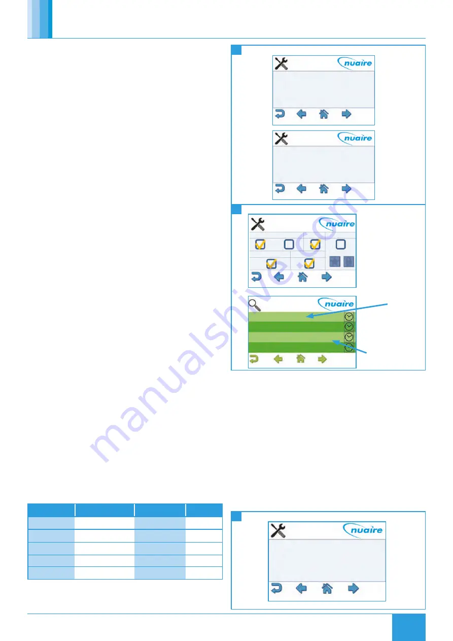
8.7.1 Choosing A Target Object

To choose a target object:

 Navigate to the settings page.

 Select the right arrow four times to reach the Select Target Device 

screen.

 Enter the physical MAC address* of the controller (Device names 

or BACnetIDs can also be used but MAC addresses are shorter).

 Select the right arrow once.

 Enter the object type of the required object (e.g. AI, AO, MSV)**.

 Enter the BACnet ID** of the object. (0-4194304).

 Select the home icon.

* This is the setting of the DIP switch on the front of the FAC controller. 
This can also be discovered by browsing to the network screen while ID 
is selected in the View Config settings screen.

** Popular object details are listed below, or use the network browser 
or see “Exposed BACnet Object List” for a full list.

Network Page Description

Object Type

Object ID

16

Room Air Temp

AV

11296

16

CO2 Level

AV

13980

16

Humidity

AV

14297

16

Active Setpoint

AV

14534

1

Fresh Air Temperature AI

10008

50 

51 

52 

Choosing Target Device

Selecting Target Device

Setting Target Device

Device Name

MAC Address

Device ID

4

0


Select Target Device

Object Type

Object ID

AI

10050


Select Target Device

TL-BRTRP-0                    0          1

Nuaire BPS ESC             4            0909501

Nuaire BPS ESC             5            0909502

Name

Write

ID

Description Status

Function

MAC Address

BACnet Device ID

8.7.2 Setting Target Object

To set the target object page as the default home page:

 Navigate to the settings page.

 Select the right arrow twice to reach the display settings screen.

 Select Home Page.

 Select Target.

 Select the enter icon.

 Select the home icon.

The BACnet type & ID will be displayed on the target page if ‘ID’ is 
selected on the ‘View Config’ settings screen.

If the target page is selected as the home page and a security 
password is set the home page will be locked. The only way to exit 
the target screen in this case is to press the Nuaire logo to the top 
right of the screen for 5 seconds.

Backlight

Home Page

Service Password

User Password

Stand by

Stand by Timer

Stand-by-OFF 

Target 

0

0

Dark

0


Select Target Device

Summary of Contents for Xboxer xbc+ Ecosmart Connect Control

Page 1: ...ust be replaced by the manufacturer its service agent or similarly qualified persons in order to avoid a hazard Precautions must be taken to avoid the back flow of gases into the room from the open fl...

Page 2: ...ent person to determine if any additional PPE is required 2 0 INTRODUCTION The information contained in this document provides details of installation operation and maintenance for installers and user...

Page 3: ...BOXER 2 HX Type C Counterflow E Enthalpy 3 Unit Size 10 15 25 45 55 65 4 Unit Layout H Horizontal 5 Filter Grade A 6 Heating Type E Electric L LPHW N No Heating 7 Heater Size H High Duty L Low Duty N...

Page 4: ...ring the offloading from the vehicle or on the site thereafter All claims for damage and or incomplete delivery must be reported to Nuaire within two days of receipt of the equipment following Nuaire...

Page 5: ...panels it is recommended that electrical and plumbing service connections to the unit are run at 90 degrees to the main air flow axis Control circuit connections must be segregated i e routed separate...

Page 6: ...C D SUPPLY DISCHARGE Unit Code Dimensions to Hole Centres mm A B C XBC10HA 1068 830 385 XBC15HA 1068 830 385 XBC25HA 1232 884 415 XBC45HA 1332 1020 447 XBC55HA 1632 1052 424 XBC65HA 1644 1054 430 Unit...

Page 7: ...250 471 302 76 XBC25 HE MS12 1250 252 302 59 XBC25 HS MS16 1600 471 302 99 XBC25 HE MS16 1600 252 302 73 XBC45 HS MS10 1050 531 360 69 XBC45 HE MS10 1050 270 360 49 XBC45 HS MS12 1250 531 360 88 XBC45...

Page 8: ...471 64 XBC25 HE MBS S 421 402 275 421 402 342 302 292 252 40 XBC25 HE MBS L 992 973 846 421 402 342 302 292 252 54 XBC45 HS MBS S 700 681 415 700 681 400 360 571 531 60 XBC45 HS MBS L 1070 1051 785 70...

Page 9: ...ds should be secured to the Unistrut channel and extended to be fixed to the four piece support brackets to be used on the underside of the attenuators Figure 15 Note once the attenuators are supporte...

Page 10: ...5 XBC65 EXHAUST RT XBC65 INTAKE RT 3 12 2 Optional Exhaust Intake Terminals 3 12 3 Terminal Part Codes 16 17 Weatherproof Kit Installation Motorised Damper Installation 3 13 Motorised Dampers If match...

Page 11: ...t at the connection points and to make sure that they run without any kinks 18 19 Damper Wiring Switch Wiring S1 S2 S3 S1 S2 S3 1 0 1 0 1 0 0 1 230V Auxiliary switch Notes Caution Power supply voltage...

Page 12: ...Unit Condensate drain connection 8 mm flexible pipe Control box Coil connections 40mm centres Access to Condensate tray and Pump IMPORTANT The condensate pump incorporates an alarm function If the wat...

Page 13: ...ure Units must not be operated without all access panels in place damage to equipment or injury to personnel may result Units must not be operated unless control interlocks are in place damage to equi...

Page 14: ...riginal CAGE CLAMP terminals blocks 5 7 4 Fitting Jumpers Terminal blocks can be connected together to increase the number of terminals at the same potential using push in jumpers In these cases the t...

Page 15: ...E G F H I 5 8 Unit Hardware Positions Diagram 29 30 Hardware Positions I O Damper Wiring 5 8 1 Hardware Position Key A Supply fan drive health B Delivery air temperature sensor C Extract air temperat...

Page 16: ...20 Document Number 671954 Nuaire Western Industrial Estate Caerphilly CF83 1NA nuaire co uk XBC with Ecosmart Connect C Control Installation Manual 31 Basic Unit Connection 5 10 Basic Unit Connection...

Page 17: ...1 07 20 Document Number 671954 Nuaire Western Industrial Estate Caerphilly CF83 1NA nuaire co uk XBC with Ecosmart Connect C Control Installation Manual 32 Controller Layout 5 11 Controller Layout Dia...

Page 18: ...ber 671954 Nuaire Western Industrial Estate Caerphilly CF83 1NA nuaire co uk XBC with Ecosmart Connect C Control Installation Manual 5 12 Wiring Diagrams 5 12 1 Unit Sizes 10 15 with No Heating 33 Siz...

Page 19: ...cument Number 671954 Nuaire Western Industrial Estate Caerphilly CF83 1NA nuaire co uk XBC with Ecosmart Connect C Control Installation Manual 5 12 2 Unit Sizes 25 65 with No Heating 34 Sizes 25 65 wi...

Page 20: ...ment Number 671954 Nuaire Western Industrial Estate Caerphilly CF83 1NA nuaire co uk XBC with Ecosmart Connect C Control Installation Manual 5 12 3 Unit Sizes 10 15 with LPHW Heating 35 Sizes 10 15 wi...

Page 21: ...ment Number 671954 Nuaire Western Industrial Estate Caerphilly CF83 1NA nuaire co uk XBC with Ecosmart Connect C Control Installation Manual 5 12 4 Unit Sizes 25 65 with LPHW Heating 36 Sizes 25 65 wi...

Page 22: ...Number 671954 Nuaire Western Industrial Estate Caerphilly CF83 1NA nuaire co uk XBC with Ecosmart Connect C Control Installation Manual 37 Sizes 10 15 with Electric Heating 5 12 5 Unit Sizes 10 15 wi...

Page 23: ...Number 671954 Nuaire Western Industrial Estate Caerphilly CF83 1NA nuaire co uk XBC with Ecosmart Connect C Control Installation Manual 38 Sizes 25 65 with Electric Heating 5 12 6 Unit Sizes 25 65 wi...

Page 24: ...Sensor When a Room Module PIR sensor is connected via the SA bus the control will automatically use this as an enable signal by default There is a non adjustable minimum run on time of 15mins for Roo...

Page 25: ...0V input is scaled to 0 100 fan speed demand This is available on IN5 only The fan speed can be adjusted in software using the LCD or a BACnet connection by adjusting the Fan Speed Demand object Fan S...

Page 26: ...turn air temperature the outside air temperature and the heat exchanger efficiency e g 13 C outside air temperature with a 23 C return air temperature will give a supply air temperature of 20 5 C The...

Page 27: ...ce in critical alarm state the unit will drive all heating and cooling outputs to 0V In the event of fan fail other functions continue as normal The critical alarm is latched and requires power cycle...

Page 28: ...Enable The state of the enable input IN8 BI 10161 N A 0 Off 1 On 9 Run on Enable Run on timer value AV 10267 0 Seconds 24 Local Calendar 0 CAL 10496 N A 0 33 Enable via Schedule Enabled via Schedule M...

Page 29: ...d Dead band for temp control AV 10266 3 Degrees Celsius 32 SetPoint Op Setpoint operation MSV 10214 Software Setpoint Only 1 Last Changed 2 Software Only 3 Last Changed with Timeout 19 Setpoint Timeou...

Page 30: ...Speed Schedule Current state of the Fan Speed Demand Schedule object AV 17830 0 Percent 44 Fan Override Operation Chooses the operation of the 3 speed fan override MSV 17975 Override Has Priority 1 Ov...

Page 31: ...A Degrees Celsius 4 RM201 Humidity The Humidity at RM address 201 AI 10077 N A Percent Relative Humidity 7 RM201 Setpoint The setpoint at RM address 201 AV 10083 N A Degrees Celsius 3 RM202 Temp The t...

Page 32: ...he state of Alarm Circuit 1 BI 10167 N A 0 Alarm 1 Normal 20 Alarm Circuit 2 The state of Alarm Circuit 2 BI 10170 N A 0 Alarm 1 Normal 11 High Temp Alarm Supply temp which will trip the high supply a...

Page 33: ...to be changed The instance number range is 1 4 194 303 222 Ecosmart Connect controllers use a MSTP network for communication and are assigned a MSTP address 4 127 by the dip switch located on the fro...

Page 34: ...e 7 Case 5 Priority 1 Null Priority 2 Null Priority 3 Null Priority 4 Null Priority 5 Null Priority 6 Null Priority 7 Null Priority 8 Null Priority 9 Null Priority 10 Null Priority 11 Null Priority 12...

Page 35: ...nstance 10185 Object Type AO Present Value 0 State Text Volts Object Properties Object Name Enable Object Instance 10288 Object Type MSV Present Value On State Text Off On Object Properties Object Nam...

Page 36: ...has a USB 2 0 Type B receptacle which is only used to obtain power from a computer or USB adapter A mains adapter and cable is supplied The router connects to the FC bus via screwed terminals 8 2 BACn...

Page 37: ...49 ESCO LCD Navigating the ESCO LCD 8 5 Navigation Cancel Quit and moves to the previous section Home Shortcut to the configured Home Page Back Moves to the previous page in the same section Forward...

Page 38: ...bject within the entire network 8 7 1 Choosing A Target Object To choose a target object Navigate to the settings page Select the right arrow four times to reach the Select Target Device screen Enter...

Page 39: ...the settings page Select the right arrow twice to reach the display settings screen Change the user password a 4 digit number The user password will now be requested each time a locked object is writt...

Page 40: ...n be accessed by selecting the alarm icon Alarm events are logged with a date and time Nor represents a change to a normal state Ala represents a change to an alarm state The text in parentheses denot...

Page 41: ...he value of the Max_Master property of the node s Device object 127 APDU Time The APDU Timeout property defines the amount of time in seconds the FAD waits for responses from other devices 3 8 8 2 Dis...

Page 42: ...hen accessing the Network View the FAD launches a Network Discovery function The purpose of this function is to find other BACnet devices residing on the same MS TP trunk The maximum number of devices...

Page 43: ...s 9 2 4 Room Humidity The ESC RM 2 TDH 120 model includes a push button on the face of the network sensor to allow occupants to view the temperature and relative humidity of the zone Pressing the push...

Page 44: ...dard Sensor Small Room Module Dimensions Large Room Module Dimensions CO2 Sensor SA SA Bus Com SA Power from Controller 15 VDC SA Bus Screw Terminal Block Network Sensor COM SA PWR Screw Terminal Bloc...

Page 45: ...YES YES YES YES 199 fixed Max of 1 per controller Group 2 Max of 4 Per Controller ESCO TS 80x80 YES 200 203 ESCO THS 80x80 YES YES 200 203 ESCO TDS 80x80 YES YES 200 203 ESCO TDHS 80x80 YES YES YES 2...

Page 46: ...Angular Degrees up to a distance of 15 ft 4 6m Based on a clear line of sight Ambient Operating Conditions 10 to 30 C 10 to 90 RH Temp Probe 10 to 60 C Ambient Storage Conditions 20 to 60 C t to 95 R...

Page 47: ...adaptor 3 way female RJ12 adaptor RJ12 Sensor jack Cable Type Pre fabricated 3 twisted pair with RJ12 Plugs 26AWG Room Module Room Module RJ12 Plug RJ12 Plug Room Module Sensor SA Bus RJ 12 Modular Ja...

Page 48: ...trickle the fans at all times 10 1 4 Setting Supply Air Temperature If a room module is fitted with an integral LCD the air off temperature is set by the end user via the adjustment dial e g ESCO TDS...

Page 49: ...ocessed in energy from waste centres Remaining Items can be further segregated and processed in accordance with the zero waste hierarchy Please call After Sales Support for further information on item...

Page 50: ...re supplied with the specified equipment e g wall mounting brackets They are to be used to support the equipment only Other system components must have separate provision for support 4 3 Flanges and c...

Page 51: ...51 21 07 20 Document Number 671954 Nuaire Western Industrial Estate Caerphilly CF83 1NA nuaire co uk XBC with Ecosmart Connect C Control Installation Manual NOTES...

Page 52: ...52 21 07 20 Document Number 671954 Nuaire Western Industrial Estate Caerphilly CF83 1NA nuaire co uk XBC with Ecosmart Connect C Control Installation Manual NOTES...

Reviews: