11
30. 06. 20. Document Number 671948
Nuaire |
Western Industrial Estate
|
Caerphilly
|
CF83 1NA
|
nuaire.co.uk
XBC+ with Ecosmart Classic (E) or No (N) Control
Installation Manual
3.14 Constant Pressure (CP) Setup
Where applicable XBC Ecosmart constant pressure sensors are supplied
to control the static pressure at the extract fan inlet. As a single fan
speed control PCB is used within these units the supply fan will mirror
this change in extract fan duty. This change in supply duty can be offset
to become proportionate to the “o ADJ” pot setting (Section 5.4).
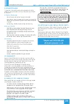
This set up is suitable for the majority of applications. When ancillaries
with high pressure losses are fitted to the inlet side of the fan, the low
pressure tapping must be moved from the fan chamber to a location
upstream of the ancillaries, as shown below in Figure 19.
Failure to do this will result in excessive pressure being applied to the
dampers at the rooms when the system is running in trickle mode.
3.15 Filter Pressure Switch
XBC units come with pre fitted pressure tappings for use with the
dirty filter alarms (supplied loose) on both the supply and extract air
streams. The IP54 pressure switch is equipped with a red visual LED
alarm which will illuminate when the pressure reading surpasses that
set by the adjustable knob.
3.15.1 Mounting Pressure Switch
Using the four mounting lugs provided, mount the pressure switches
to a flat vertical surface using fixings appropriate for the surface. Any
fixings used must have a maximum diameter of 8.0 mm. Do not tighten
the fixings so much that the base of the device is deformed.
3.15.2 Connecting Pressure Tubing
Pressure tubing must not be kinked. Pay particular attention to this
point if running hoses over an edge, it is better to form a loop.
For connection to the pressure switch, two fittings inherent in the
housing are provided for hoses with an internal diameter of 6.0 mm.
•
Connect a hose from the after filter (AF) pressure tapping to socket
P1 which is located on the lower section of the housing.
•
Connect a hose from the before filter (BF) pressure tapping to
socket P2 which is located on the middle section of the housing.
After you have installed the hoses, it is essential to check them for
tightness of fit at the connection points and to make sure that they
run without any kinks.
18
19
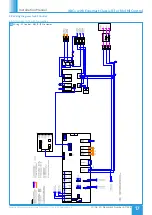
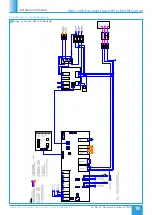
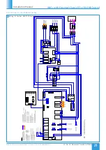
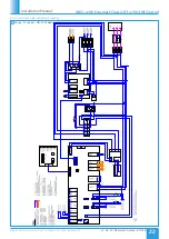
Damper Wiring
Switch Wiring
S1 S2
S3
S1
S2
S3
1
0
1
0
1
0
0
1
230V
Auxiliary switch
Notes:
Caution Power supply
voltage.
Other actuators can be
connected in parallel.
Please note the
performance data
Direction of rotation
OP
CL
N
RET
Ecosmart Board Connection
1
2
3
S1 S2 S3
0
1
0...100%
A fan delay of 1 minute is
imposed to enable the damper
to open. To override the delay
fit a link here.
N
L
2
1
3
0
S1 S2 S3
1
0...100%
N
L
0
Cable colours:
1 = Blue
2 = Brown
3 = White
S1 = Violet
S2 = Red
S3 = White
3.15.3 Setting Switch Pressure
Make absolutely certain that there is no voltage on the electrical
connections before you carry out any setting on the pressure switch,
there is the possibility of an electric shock if you accidentally touch live
parts.
Nuaire recommend the pressure switch be set to trigger when the
filters experience a 125 Pa increase above the clean filter resistance for
the largest commissioned airflow rate. Use the adjustment dial to set
the pressure at which the switch will trip. When the pressure falls below
this set value, the switch returns to its resting position.
3.15.4 Switch Wiring
The cable gland is designed for cables with alternative sheath diameters
of 7 mm or 10 mm. Only use these sizes. Otherwise the screw cable
connection cannot seal adequately. The connections are intended for
6.3mm crimp-type sockets.
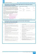
Remove switch cover. Wire the main unit to the terminal block within
the switch as per the below wiring diagrams (Figure 19) ensuring the
feed line is fused to suit Max 1.5A / 250 Vac. Refit switch cover.
Schematic Diagram
Pressure Sensor Internals
2 - NO
3 - C
1 - NC
3 - C Contacts 2 - NO
when the difference between
positive & negative pressure
is equal to the set pressure.
Customer 240 V
Connection
Customer 240V
Connection
Internal Connection
Customer Connection
*Note 1: NC has been
blanked off.
*Note 2: Pressure setting
of 125Pa above clean filter
pressure is recommended.
*Note 3: If a different
arrangement is required,
then the internal LED con-
nections can be removed.
240 V
Indicator
240 V
Indicator
Sensor Diagram
2 - NO
1 - NC
*Note 2
*Note 3
*Note 1
Differential
Pressure
Setting
3 - C


