


Page 27
NDFL100-38 / BR003211 / Rev. 220900A
R
OUTINE
M
AINTENANCE
Switch off electrical supply and gas/oil supplies to
the burner.
Combustion Air Fan
Clean the blades regularly with a stiff brush. Access
is obtained through the burner top cover. Care
should be taken to avoid damaging the fan blades.
Check that the air inlet into the fan is clean.
Inner Assembly
Remove the 2 locking nuts and washers securing
the hinged extension.
Open the hinged extension and disconnect the
ignition electrode H.T. leads.
Disconnect the manifold oil feed at the flexible
connection.
Remove the 3 Din plugs from the triple oil valve
assembly
having first made note of their
positions
.
Loosen the 2 nuts securing the oil inner assembly
manifold to the hinge flange and slide the oil inner
assembly backwards until it clears the burner.
Remove the cap head screw securing the gas inner
assembly to its manifold. Carefully withdraw the
inner assembly from the hinged extension.
Air Diffuser and Gas Nozzle
Clean using a stiff brush.
Ignition Electrodes
Clean and check the electrodes are not cracked
or worn. Renew if necessary.
Check the settings of the ignition electrode and
reset if necessary, details are shown on page 6.
Oil Nozzles
The oil nozzles should be replaced after
approximately 2000 hours operation.
Filters
A filter is fitted within the pump. To gain access,
remove pump and endplate. Withdraw filter and
clean it in paraffin, or similar solvent. Replace fil-
ter and pump endplate.
A filter should be fitted in the fuel supply pipe. If
fitted with a disposable element this should be
replaced at least once per year. If the filter has a
re-useable element this should be cleaned at suit-
able intervals.
It will be necessary to remove air from the system
after the above operations by bleeding the pump.
Fan Motor
The motor requires no maintenance. It has bear-
ings that are factory-lubricated for the life of the
motor.
Replacement of Control Valve SKP20
Should the SKP20 valve require replacing due to
mechanical or electrical failure, then the governed
gas pressure will have to be reset. It is essential
that only qualified combustion engineers
undertake replacement of these components.
F
AULT
F
INDING
Any modifications to the installation or component
settings resulting from actions suggested below may
require the re-establishment of the various settings.
During the purges and firing cycles the MPA control
checks for both internal and external faults. Should
a fault be found the control causes a safety
shutdown and flashes an error code on the display.
The last six error codes are kept and can be
obtained from the service mode screen ten
onwards.
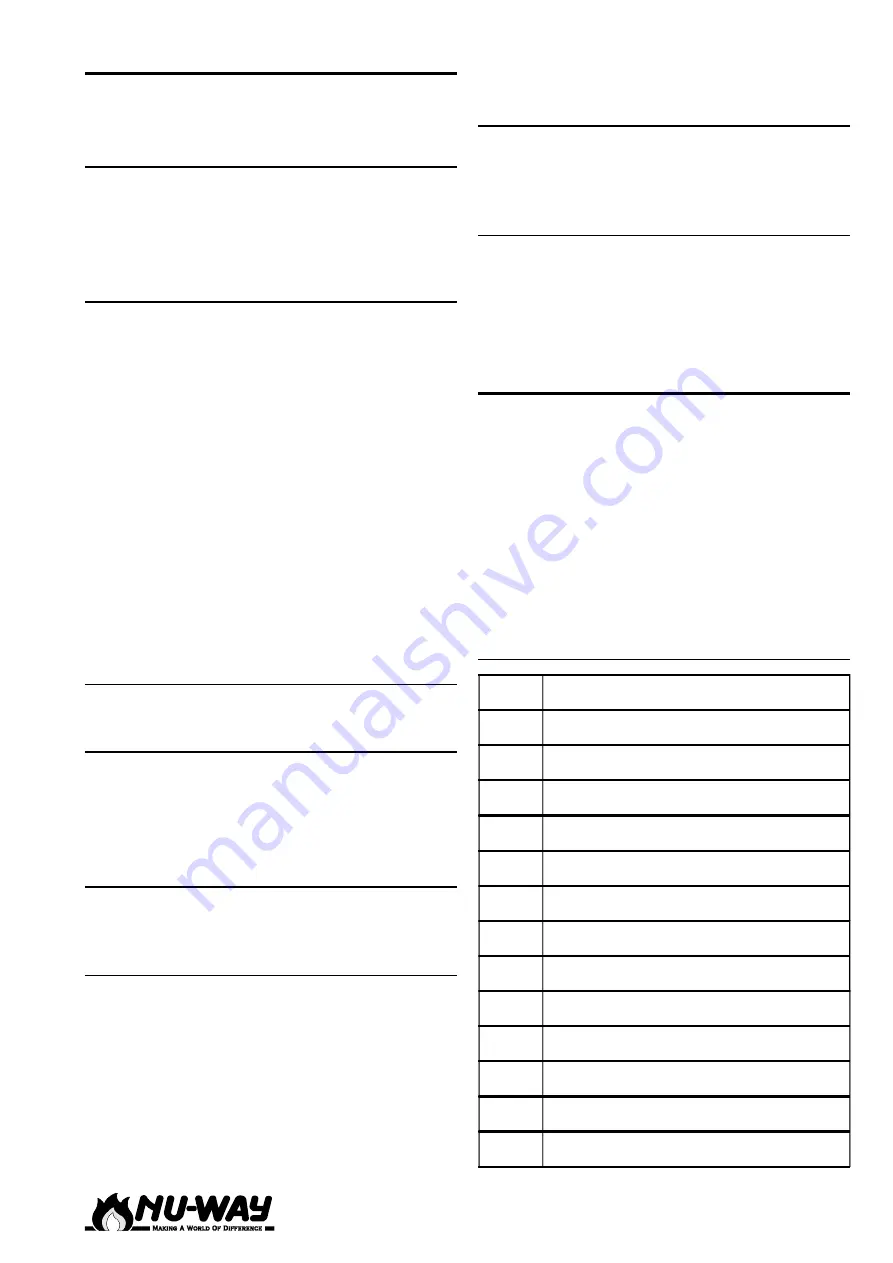
MPA Error Codes
&RGH
(UURU'HVFULSWLRQ
+ $LUSUHVVXUHVZLWFKQRWLQUHVWSRVLWLRQ
+ $LUSUHVVXUHVZLWFKIDLOXUH
+ *DVSUHVVXUHVZLWFKIDLOXUH
+ 1RIODPHDIWHUVDIHW\SHULRG
+ ([WUDQHRXVOLJKW
+ )ODPHIDLOXUHGXULQJRSHUDWLRQ
%+ 6KRUWFLUFXLWLQ893KRWRFHOO
+ )LUVWYDOYHOHDNLQJ
+ 6HFRQGYDOYHOHDNLQJ
+ *DVVHUYRPRWRURUFRGLQJSOXJ
+ $LUVHUYRPRWRUDFNQRZOHGJHPHQW
+ *DVVHUYRPRWRUDFNQRZOHGJHPHQW
$+ $LUPRWRUSRVLWLRQRXWRIWROHUDQFH


