background image

 
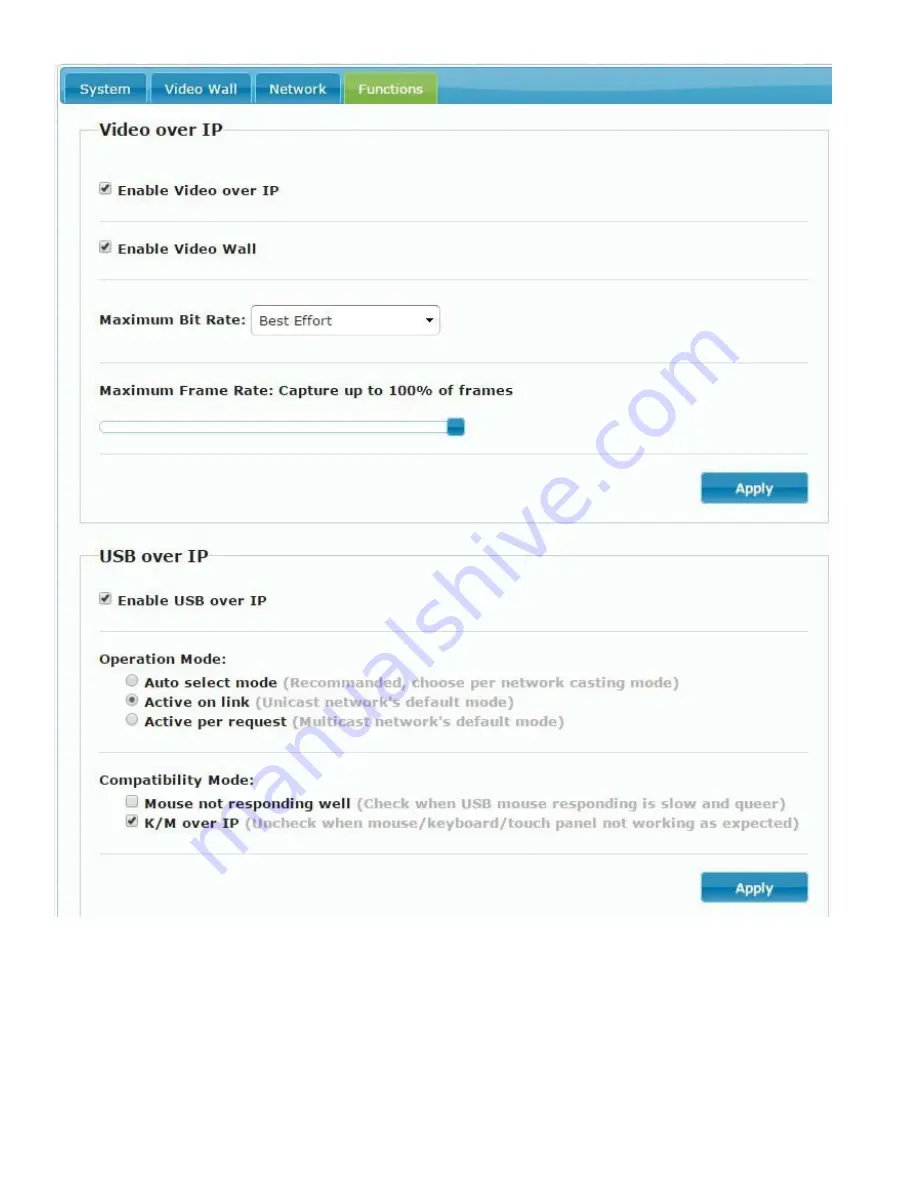
Functions for Transmitter:


Video over IP


Enable Video over IP: This function sets up the video signals sent from over the network. 


Enable Video Wall: This function sets up the video wall (default is not checked). 


Maximum Bit Rate: Set maximum bit rate. 


Maximum Frame Rate: Set maximum frame rate. 


USB over IP


Enable USB over IP: Enable/disable USB extender function. 


Operation Mode: Set USB operation mode. 

Recommend Auto select mode.


Compatibility Mode: Set USB compatibility mode. 

35 


Summary of Contents for XTENDEX Series

Page 1: ...ST IPUSBVD L R VW VGA DVI USB KVM Extender Over IP with Video Wall Support User Manual Transmitter Local Unit XTENDEX Series Receiver Remote Unit ...

Page 2: ...SB Hot Key Function 8 IR Remote Control Setting 9 IR Remote Control Operation 10 Caution when using IR Menu 13 Keypad Control 15 RS232 Control 15 Troubleshooting 20 APP Control Function 21 IP Setting 22 Bonjour plug in installation 23 Web configuration 26 System 26 Video Wall 29 Network 34 Functions for Transmitter 35 Functions for Receiver 37 Firmware Update Instruction for ST IPUSBVD VW 38 Speci...

Page 3: ...100 meters Built in video converter and switch supports digital DVI and analog VGA Connect a VGA USB computer and DVI USB computer and switch between sources using the front panel buttons o Both the transmitter and receiver support VGA and DVI monitors at the same time Supports USB 2 0 1 1 devices o Keyboard and mouse are hot pluggable o Connect a mouse keyboard flashdrive web camera or touchscree...

Page 4: ...Applications Point to Point Connection 2 ...

Page 5: ...Point to Many Connection Many to Many Connection Local Unit Remote Units Remote Units Local Units 3 ...

Page 6: ... Press for 1 second Carry Decomposition Press for 3 seconds Lock Unlock Panel Buttons When OSD is not displayed Press and hold then power the unit ON Factory Default Engineering Mode Definitions Reduce Number decrements the channel or the function number down from IR Menu Pg 8 Increase Number advances the channel or the function number up from IR Menu Pg 8 4 ...

Page 7: ... after setting Set to DVI single input output mode Set to VGA single input output mode Set to VGA DVI dual input output mode Menu and and Front Panel LED Indication Status Panel LED Status Meaning ON Green On Boot completed Flash Twice Booting Flash Slowly Transmitter stop link Receiver video output is turned OFF Breathing Fading Screen saver mode not available for transmitter Link Blue On Connect...

Page 8: ... system setting activity is occurring 2 IR Control disabled 3 Transmitters channel conflict 4 DHCP server not found 5 Restore to factory defaults 6 Engineering mode Firmware update mode 7 Manufacture setting mode 8 Aux system stopped 9 Aux system firmware boot sector error 10 Aux system firmware type error Note Messages 7 10 are for factory use only They are not likely to be seen in normal use 6 ...

Page 9: ... 72 120 1600x1200 UXGA 81 57 105 800x600 SVGA 66 49 82 640x480 VGA 43 29 56 The above bandwidth chart does not include USB transmission USB uses up to 50 Mbps when transferring mass data System scalability is limited only by uplink and stacking connector bandwidths For example under a Gigabit Ethernet network the total flow must not exceed 1000Mbps to avoid any delay of video streaming If the vide...

Page 10: ...54 X X subnet mask 255 255 0 0 to transmitters and receivers when no DHCP server is present We recommend using Static IP mode when using APP or PC software control to prevent any IP change problems USB Hot Key Function Multicast mode supports multiple USB keyboard and mice in each receiver but only one USB FLASH drive hard disk can be used at the same time In order to establish a USB FLASH drive o...

Page 11: ...er 7 for the transmitter to complete the setting point away from the transmitter or receiver IR Remote Control Button Symbol Button Receiver Function Transmitter Function POWER Turn Off On Video Output Connect Disconnect Receiver Setup Remote Control ID MENU Menu selection input numbers after press menu button UP Increase Value DOWN Reduce Value LEFT Carry RIGHT Decomposition ENTER Enter Show Chan...

Page 12: ... for Transmitter Press MENU A Switch to message mode to receive response instead of OSD Press MENU B Switch to extender mode IR Menu Function List No Menu Description Option Remark RX TX 0 System Information System Information V V 1 Network Information Network Information V V 2 Function Information Function Information V V 3 Control Information Control Information V V 4 Video Audio Information Vid...

Page 13: ...HD 1080p 50Hz 5 Customize 0 X 42 Audio Select TX Audio Input Select RX Audio Output Select 0 Digital 1 Analog 2 Auto 2 2 43 Analog Input Volume Analog Input Volume 0 Mute 1 100 Volume 85 85 44 Analog Output Volume Analog Output Volume 85 85 45 Video Quality Video Quality setting 0 Graphic Mode 1 5 Mode 1 5 6 Video X 6 46 Anti Dither Anti Dither setting 0 Disable 1 2 Mode 1 2 X 0 47 EDID Update Upd...

Page 14: ...de 0 Disable 1 Enable 1 1 71 Menu Item Advanced Menu Display Hide Advanced Menu 1 1 72 Screensaver Screen Saver setting 0 X 73 Screen Off Option Behavior After Screen Off 0 No Option 1 Mute Analog Audio 2 Stop Connection 1 X 74 Diagnostic Information Diagnostic Information 0 Disable 1 Enable 1 X 75 Message Redirect Message Redirect to Auxiliary X 1 76 Command Redirect Command Redirect to Auxiliary...

Page 15: ...ibed later in this manual Menu 35 For monitors that detect HDMI 5V causing them to enter sleep mode Menu 36 Turn OFF monitor by CEC command via RX Menu 40 In VGA DVI dual input mode When input video loss exceeds 8 seconds the Transmitter will switch to another input automatically When the input is from DVI source the Transmitter will convert DVI to VGA loop out automatically Menu 41 Pass Through t...

Page 16: ...80 86 With this you can force the selected feature not to follow the channel that is being switched to This is only available when free routing is enabled For example you could set the audio to come from Transmitter 2 exclusively by set the audio routing function to 2 When you do this and you switch the Receiver to view video from Transmitter 3 you will still hear audio from Transmitter 2 Default ...

Page 17: ...ll receivers to one transmitter to avoid an RS232 connection break caused by video channel switching Command format CMD_Address Command Parameters Address command and parameters are characters not hex code Enter LF or CR LF is required to execute the command All associated receivers will run the command and parameters We also add 3 kinds of user defined numbers except MAC IP Device No Group No Par...

Page 18: ...E DISABLE Enable disable video extension ROUTING Status of video routing ROUTING FOLLOW 0 999 Set video routing follow or specified SELECT Status of video input output mode SELECT 0 2 Set input output 0 DVI 1 VGA 2 DVI VGA SCALER Status of video output resolution SCALER 0 4 5 Set output resolution 5 customize CUSTOMIZE Status of customize resolution CUSTOMIZE Set customize resolution QUALITY Statu...

Page 19: ...pecified REQUEST Request USB access multicast only KM FUNC Status of keyboard mouse extension KM FUNC ENABLE DISABLE Enable disable keyboard mouse extension RS232 FUNC Status of RS232 extension Transmitter does not support parameter ROUTING FUNC ENABLE DISABLE Enable disable RS232 extension ROUTING Status of RS232 routing ROUTING FOLLOW 0 999 Set RS232 routing follow or specified SELECT Status of ...

Page 20: ... support parameter DISCONNECT DISCONNECT Disconnection keep routing channel STOP Stop all connection Include routing channel MULTICAST Status of multicast MULTICAST ENABLE DISABLE Disable unicast JUMBO_FRAME Status of Jumbo Frame JUMBO_FRAME ENABLE DISABLE Enable disable Jumbo Frame IP_MODE Status of IP mode IP_MODE 0 2 0 Auto 1 static 2 DHCP IP Status of static IP address IP xxx xxx xxx xxx Set s...

Page 21: ...th last 6 digits MAC Address is F01234 response OK HEX code 3C 41 43 4B 5F 4D 38 36 31 32 33 34 3C 20 4F 4B 0D 0A CMD_I0A12 CHANNEL 3 Set receiver which IP Address is 169 254 10 18 to Channel 3 HEX code 3E 43 4D 44 5F 49 30413132 3E 20 43 48 41 4E 4E 45 4C 20 33 0D 0A ACK_I0A12 OK Receiver which IP Address is 169 254 10 18 response OK HEX code 3C 41 43 4B 5F 49 30 41 31 32 3C 20 4F 4B 0D 0A CMD_G3...

Page 22: ...reen or the last still image for a few seconds 10 Fast switch mode might cause the screen or audio to briefly behave abnormally when switching channels 11 When output resolution is fixed the screen or OSD might be cutoff a little if the source resolution is much different than the receiver output like 1080p downscale to 720p 12 For high resolutions like 1080p the OSD response will be delayed a lit...

Page 23: ...evice https play google com store apps details id com sct sctcontrollcenter1 iTunes Download Link For Apple Device https itunes apple com us app stream videowall management id1420342140 mt 8 Google Play Download QR code iTunes Download QR code For APP instruction please download from our website 21 ...

Page 24: ...ient page please refer software instruction Methods to get the IP address of transmitter 1 Connect the monitor with the receiver connect the receiver with the transmitter and set them in the same channel Do not connect video source to transmitter the remote IP will display on the right bottom of the screen 2 Install Internet Explorer browser plug in Bonjour Click the device name to enter web setti...

Page 25: ...tallation a Click BonjourSDKSetup exe to install Bonjour plug in for Internet Explorer browser b Click Next to continue c Click I accept the terms in the license agreement and Next to continue d Click Next to continue 23 ...

Page 26: ...erties then right click on Local Area Connection Properties then double click on Internet Protocol TCP IP to view the network settings of the PC as below IP address 169 254 111 111 sub mask 255 255 0 0 h Make note of the network settings for the PC The PC should be on the same subnet as the Transmitters and Receivers 24 ...

Page 27: ...r Bars Bonjour Double click on HTTP on ast3 tx yyyy where y channel of transmitter or HTTP on ast3 rx yyyyyyyyyyyy where y MAC address of receiver The configuration software in the transmitter or receiver will open Click Network page to see the IP address of the transmitter or receiver Make changes as needed Restart to take effect For newer versions of Internet Explorer Bonjour will open as a side...

Page 28: ...onfiguration System Version Information Firmware version and other information Update Firmware To perform a firmware update refer to the procedure on page 38 The web interface is not used for this feature 26 ...

Page 29: ...ities Factory Default Set system to factory default Reboot Reboot system Default EDID Set EDID to default 1080p 7 1 channel audio Console API Command Enter Console API command to change setting or control 27 ...

Page 30: ... Statistics Indicates system status 28 ...

Page 31: ...ze and Position Layout Set scale of video wall and position of monitor Vertical monitor count 1 8 Horizontal monitor count 1 16 Row position 0 7 Column position 0 15 Preferences Set extension way and rotation Select the video fit in the screen or stretch out and rotate angle Apply To 1 All Configure all Transmitters and Receivers in the list 2 This Local Current device which you are logged into by...

Page 32: ... Advanced Setup 30 ...

Page 33: ...up as follows 1 In Basic Setup select Vertical and Horizontal Monitor Count 2 In Advanced Setup choose the target unit in the video wall to control Step 2 Control Options Reset to Basic Setup Press Reset if mistakes are made in the configuration Stretch Type 31 ...

Page 34: ...le to 0 180 270 degrees of the video output Screen Layout Row x Column Set up the number of vertical and horizontal monitors based on the video wall layout Vertical number 1 8 and horizontal number 1 16 Row Position Setup the row position of monitor number from 0 to the total number of vertical monitors 32 ...

Page 35: ...al Scale Up Horizontal Shift Set the video horizontal shift Left or Right by pixels Vertical Shift Set the video vertical shift Up or Down by pixels Horizontal Scale Up Set the video horizontal scale up by pixels Vertical Shift Scale Up Set the video vertical shift scale up by pixels Consol API Command Input Linux command to perform an advanced setup 33 ...

Page 36: ...e Static or DHCP mode Notice If there is no DHCP server in the network the host client will keep rebooting You need to set the host client to factory default Press and hold Channel button then power ON power and link LED will flash Casting Mode Could be set to Multicast or Unicast mode default is Multicast When using Multicast mode please check the Auto select USB operation mode per casting mode b...

Page 37: ...e Video Wall This function sets up the video wall default is not checked Maximum Bit Rate Set maximum bit rate Maximum Frame Rate Set maximum frame rate USB over IP Enable USB over IP Enable disable USB extender function Operation Mode Set USB operation mode Recommend Auto select mode Compatibility Mode Set USB compatibility mode 35 ...

Page 38: ...rial over IP Enable Serial over IP sets up Serial RS232 signal sent over the network Operation Mode Default is Type 2 Recommended Dumb redirection Baudrate Setting for Type 2 default is 115200 8 None 1 36 ...

Page 39: ...output mode or select Customize and input 8 Hex values for more video output resolution and refresh rate selections 1 80000004 HD 720p60 2 81000061 WXGA 1366x768 60 3 81000040 WXGA 1440x900 60 4 81000051 WUXGA 1920x1200 60 5 8100003C SXGA 1400x1050 60 Timeout for Detecting Video Lost Please do not change this Turn off screen on video lost Please do not check this box USB over IP Enable USB over IP...

Page 40: ... RS232 Cable female to male wired straight through pins 2 3 and 5 connected to connect the PC to the ST IPUSBVD VW Local or Remote 3 After the Local or Remote boots up run the ISP exe program select the COM Port of the PC and click Connect 4 After making connection the Link Device will show the name of MCU Browse to the st ipusbvd l vxxxxxxxx UP for the local unit or st ipusbvd r vxxxxxxxx UP for ...

Page 41: ...ew seconds 8 Now restore the unit to default settings one of two ways A On the front panel press Menu then Minus then Minus again then plus and minus at the same time B Using the IR remote press Menu then press 333 then press Enter This method only works on the Remote Unit The ST IPUSBVD VW will now be ready to use D st ipusbvd l v2 89 190830 UP D st ipusbvd l v2 89 190830 UP 39 ...

Page 42: ... Typical No USB Device Power Supply 100 to 240 VAC at 50 or 60Hz DC 5V 2A AC Adapter Operating Temperature 32 to 131 F 0 to 55 C Storage Temperature 4 to 185 F 20 to 85 C Operating Storage RH 95 Dimensions WxDxH i n 7 48x5 06x1 57 190x129x40mm 6 57x4 07x1 57 167x104x40 mm Weight 650g 480g Regulatory Approvals CE RoHS RS232 Cable Connector Pinout PC to Local Unit D DB B9 9M M M Ma al le e D DB B9 9...

Reviews: