background image

8

For models KEEMUX-Sx-O (with OSD):
            1.  Make sure the KEEMUX-Sx-O is completely disconnected from all computer components.    Be sure to
                 unplug the KEEMUX-Sx-O from the electrical outlet.
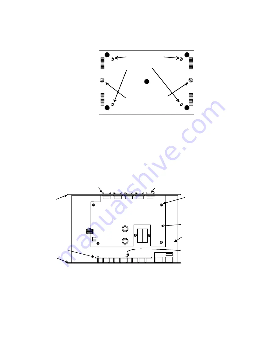
            2.  Remove the two philips-head screws from the underside of the KEEMUX-Sx-O that hold the plastic
                 case together.   Remove the 4 torx-head screws from the underside as well.    These hold the lower circuit
                 board to the plastic case.   Turn the KEEMUX-Sx-O back over and set it on a firm and flat surface.


3.  Remove the top half of the plastic case from the KEEMUX-Sx-O.

NOTE:  Before proceeding, it is important to discharge any static charge you may be carrying by touching any large   metal object
(away from the KEEMUX-Sx-O).

            4.  Firmly grasp the front and rear panel and slide the entire assembly out of the lower case.
            5.  Remove the jack screws from the video and monitor connectors on the rear panel.   Remove the rear
                 panel from the assembly.
            6. The uppermost board is the video board.   Remove the 4 hex nuts securing the video board to standoffs.

Torx-head screws
holding in the digital 
board

Philips-head screws
holding plastic case
together

View of bottom of plastic case

Nuts (4) secure the circuit board
to the standoffs.

Video Board

Digital Board

15HD Connector

Overhead view of video board on top of digital board.

The jumper block is located
below the LED board.

LED Board

Jack Screw

Rear  Panel

Front Panel

Summary of Contents for KEEMUX-Sx

Page 1: ...yboard Control 5 SCAN MODE 5 BROADCAST MODE 5 Keyboard Updating 5 How To Disable Operating Modes 6 Technical Specifications 10 Troubleshooting 10 Warranty Information 10 17 NETWORK TECHNOLOGIES INCORP...

Page 2: ...ase from Network Technologies Inc MF male female connector INSTALLATION 1 Turn OFF power to all computers that will be connected to the NTI Switch before connecting or disconnecting any cables WARNING...

Page 3: ...uration Table 1 default settings Keyboard Mouse type SW7 SW8 SUN ON OFF CASCADING The SUN switch can be expanded to access up to 128 CPU s by cascading multiple units together Up to 8 SUN switches can...

Page 4: ...ttings SW2 SW3 SW4 MASTER SLAVE OFF OFF OFF 1 slave attached Unit 1 OFF OFF ON 2 slaves attached Unit 2 OFF ON OFF 3 slaves attached Unit 3 OFF ON ON 4 slaves attached Unit 4 ON OFF OFF 5 slaves attac...

Page 5: ...example t002 would set time out to 2 seconds Pxx Selects a specific port xx port number as a two digit number ex p01 p08 p15 etc NOTE YOU MUST EXIT COMMAND MODE TO TYPE TO A COMPUTER TO EXIT COMMAND M...

Page 6: ...9 to disable the desired mode s If the unit is in a plastic case the digital board is located on the bottom of the case requiring the user to partially disassemble the unit to gain access to the jump...

Page 7: ...the standoffs With it loosened grasp firmly the video board and front panel at the same time and slide the front panel up out of the slots in the plastic case that support it Once clear of the case pi...

Page 8: ...harge any static charge you may be carrying by touching any large metal object away from the KEEMUX Sx O 4 Firmly grasp the front and rear panel and slide the entire assembly out of the lower case 5 R...

Page 9: ...cess to re assemble the KEEMUX Sx or KEEMUX Sx O Be particularly careful about connecting the ribbons back to the headers they were removed from and to fully insert the ribbons to the headers Note The...

Page 10: ...YS TURN POWER ON IN THIS SEQUENCE WARRANTY INFORMATION The warranty period on this product parts and labor is one 1 year from the date of purchase Please contact Network Technologies Inc at 800 742 83...

Reviews: